




























Chassis dimensions
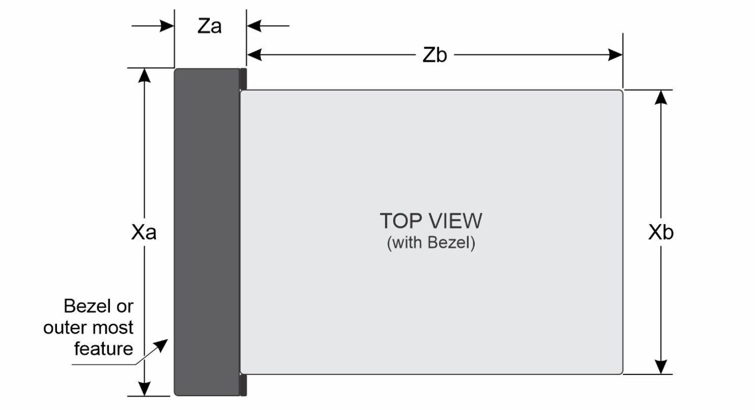
| Xa | Xb | Y | Za | Zb |
|---|---|---|---|---|
| 482.6 mm (19 inches) | 448 mm (17.63 inches) | 87.05 mm (3.42 inches) | 102 mm (4.01 inches) with bezel | 430 mm (16.92 inches) |
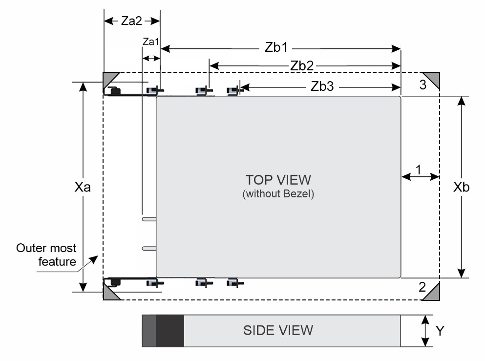
| Xa | Xb | Y | Za1 | Za2 | Zb1 | Zb2 | Zb3 |
|---|---|---|---|---|---|---|---|
| 482 mm (18.97 inches) includes rack mount ear. | 448 mm (17.63 inches) | 87.05 mm (3.42 inches) | 30.4 mm (1.19 inches) without bezel | 89 mm (3.50 inches) with cable management kit included | 423 mm (16.65 inches) | 343 mm (13.50 inches) | 293 mm (11.53 inches) |
- Minimum exhaust gap (between
chassis rear and cabinet’s rear door) required for thermal performance:
- 50 mm minimum for ambient temperatures up to 55°C
- Four post rack.
- 19-inch or 23-inch width cabinet boundary and 600 mm (23.62 inches) minimum cabinet depth.
- The outer most feature (Za2) is an optional rack ear cable management arm. This can be replaced with short depth rack ears.
- Full depth of the chassis (without bend radius) would be Za1 + Zb1 or 30.4mm + 423mm for a total of 453.4mm (17.88 inches).
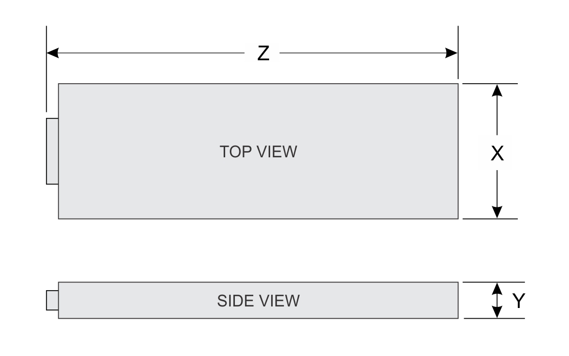
| X | Y | Z |
|---|---|---|
| 184.8 mm (7.27 inches) | 82.95mm (3.26 inches) | 431.13mm (16.97 inches) |
System weight
Chassis weight XR8000r
| System configuration | Maximum weight (with all SSDs) |
|---|---|
| Weight of chassis without sleds | 5.82 kg (12.8 pound) |
| Weight of chassis with 2 sleds - Network optimized configuration | 22.8 kg (50.26 pound) |
| Weight of chassis with 2 sleds - Flexible configuration | 26.56 kg (58.55 pound) |
| System configuration | Maximum weight (with all drives/SSDs) |
|---|---|
| Network Optimized configuration | 5.9 kg (14 pound) |
| Flexible configuration | 7.78 kg (17.15 pound) |
| Chassis weight | Description |
|---|---|
| 40–70 pounds | Recommend two people to lift |
| 70–120 pounds | Recommend three people to lift |
| ≥ 121 pounds | Recommend to use a server-lift |
Processor specifications
| Supported processor | Number of processors supported |
|---|---|
| Inten® Xeon 6 SoC processor | One |
Power Supply Units
Energy Smart power supplies have intelligent features, such as the ability to dynamically optimize efficiency while maintaining availability and redundancy. Also featured are enhanced power-consumption reduction technologies, such as high-efficiency power conversion and advanced thermal-management techniques, and embedded power-management features, including high-accuracy power monitoring. The table below shows the power supply unit options that are available for the XR8720t.
| PSU | Class | Heat dissipation (maximum) (BTU/hr) | Frequency (Hz) | AC Voltage | DC Voltage | Current (A) | ||||
|---|---|---|---|---|---|---|---|---|---|---|
| 200—240 V | 100—120 V | 277 V | 240 V | - (48—60) V | 336 V | |||||
| 1400 W -48 V DC | N/A | 5310 | N/A | N/A | N/A | N/A | N/A | 1400 W | N/A | 33.5 |
| Form factor | Output | Power cable |
|---|---|---|
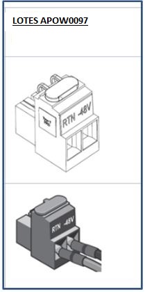
| Redundant 60 mm | 1400 W -48 V DC | Lotes connector |
Supported operating systems
The PowerEdge XR8720t system supports the following operating systems:
- SUSE Linux Enterprise Server/RT
- Canonical Ubuntu Server LTS
- Red HatEnterprise Linux/RT
- Wind River (OSVonly)
System battery specifications
The PowerEdge XR8720t system uses one CR 2032 3.0-V lithium coin cell battery.
Expansion card riser specifications
| PCIe slot | Expansion card riser | Processor connection | Height | Length | Slot width |
|---|---|---|---|---|---|
| Slot 1 | R1b | Processor 1 | Full Height | Half Length | x8 |
| Slot 2 | R1b | Processor 1 | Full Height | Half Length | x8 |
| Slot 3 | R2a | Processor 1 | Full Height | Half Length | x16 |
Cooling Fans
The PowerEdge XR8720t system supports eight cooling fans with reverse airflow. They are designed as two modules of four fans each, they are cabled and non -hot swappable
Heater Manager subsystem
Heater Manager subsystem
The XR8720t needs to support an operating temperature range of ‐20°C to 55°C with a non‐operational range of ‐40°C to 65°C. The following major components do not support an industrial range and may need to be heated before they can be powered on:
- Intel Xeon 6 SoC – minimum temperature is 0°C
- iDRAC temperature range of 0°C to 70°C
- CPLD temperature range of 0°C to 85°C
- DIMM memory – minimum temperature is 0°C
- M.2 drives – temperature range is 85°C with selected range of 0°C to 85°C
- Adapter cards – temperature ranges vary depending on the manufacturer.
- Heater power consumption consumes up to 470 W
Usage
The temperature probe and heater module assemblies will always be installed on the XR8720t.SubSystem details
The normal time to boot a system of a Linux OS prompt is in the order of 1 or 2 minutes. Because the system needs to heat before it can be booted, extra time is needed to get to the OS prompt. The total boot time for the system to the OS prompt (Linux) should not be longer than 6 minutes. This implies that the heating time must be less than 4 minutes.
In cold environments components need to be heated to an operational temperature range before they can be powered up. A small industrial range microcontroller (i.e., NXP MCXN546) called the Heater Manager subsystem is needed to measure the temperature via strategically placed temperature sensors and to apply current to one or more heating pads.
System heating is separated into a maximum of seven zones for different parts of the system. Each zone has one heating pads (connected in parallel) and one or more temperature sensors. Each zone can have a different minimum temperature but in general they are all the same and above 0C. The below table shows a potential list of heater modules in the Dell PowerEdge XR8720t.
| Heater Zone | Description |
|---|---|
| 1 | CPU‐Processor |
| 2 | DIMM A1 |
| 3 | DIMM A2 |
| 4 | iDRAC and FPGA |
| 5 | On-board M.2 drive |
| 6 | M.2 Drive 1 on the riser |
| 7 | M.2 Drive 0 on the riser |
Once the Heater Manager subsystem MCU (MCXN546) has power, it turns on the green heater LED (HM_SYS_PH_LED_N) and determines the temperature of each zone. Any zone below the threshold (e.g., 4°C) will have its heater turned on by a FET until the zone is up to temperature. The Heater Manager subsystem should continue to monitor the temperature and turn on the heater pad if the temperature ever drops below a threshold (e.g., 2°C). If no heating is required because the system is already above the heating thresholds, then the LED should still be flashed briefly for visible feedback that the system is in fact starting up. A jumper can be used to power the system without heating.
During heating, the Heater Manager subsystem may opt to use PWM to control the heating ramp and slow down rather than just turning the heater on and off. If the wattage is known for each heating zone, it is straightforward to estimate the energy that is used to heat each zone based on the time, PWM ratio, and wattage. Once all the zones are up to temperature, the “HM_SYSTEM_PH_OK_N” signal is used to turn on power to the rest of the system, and the green heater LED is turned off. iDRAC is connected to the Heater Manager subsystem with an I2C bus. IDRAC can gather metrics from the Heater Manager subsystem such as on/off time, energy that is used, and temperature statistics using the I2C interface. IDRAC may also want to query status such as zone name, zone temperature and errors.
Monitoring is added in each zone to ensure that the heating pad is present and that a FET is not shorted. A blinking amber heater LED (HM_SYSTEM_PH_FAULT_LED_N) indicates a problem with the heating sub‐system. This flashing LED is the only indication of a problem because iDRAC is not yet available for problem logging. Any failure in the heating system turns off power to the heater FETs, flashes the amber heater status LED, and initiates a system shutdown if the temperature starts to drop below the temperature threshold. If the ambient temperature is high enough (e.g., 10°C), then the iDRAC and shared NIC is powered to ensure that the problem is logged with iDRAC and is available on a remote iDRAC console.
Heater Manager subsystem LED
- LED lights Green when system pre‐heating is enabled and will turn off when system pre‐heating is completed. The Heater Manager subsystem will continue to maintain proper temperature on the system after preheating, but the LED will stay off while the system is on.
- LED flashes Amber with a 1 Hz frequency when any required heater or thermal sensor is absent or has failed.
When the OS is shut down, iDRAC enters state S5. The Heater Manager subsystem may turn on heaters as necessary. At low system temperatures iDRAC turn off the system fans to reduce the ingress of colder ambient air. Such as a zone not increasing its temperature when heated.
Memory specifications
| DIMM type | Rank | Capacity | Single processor | |
|---|---|---|---|---|
| Minimum system capacity | Maximum system capacity | |||
| DDR5 RDIMM | Single rank | 16 GB | 32 GB | 128*GB |
| Dual rank | 32 GB | 64 GB | 256*GB | |
| Dual rank | 64 GB | 128 GB | 512*GB | |
| Dual rank | 96 GB | 192 GB | 768*GB | |
| Memory module sockets | Speed | ||
|---|---|---|---|
| HCC processor - 4,
288-pin XCC* processor - 8, 288-pin |
6400 Mt/s |
Drives
- Up to three NVMe non-hot swappable M.2 drives.
USB Ports and connectors
USB Ports
There is one USB 3.0/2.0 port and one USB-C port on the front of the sled.
All USB ports follow USB specifications. The maximum output currents for USB 2.0 and USB 3.0 are 0.5A and 0.9A, respectively.
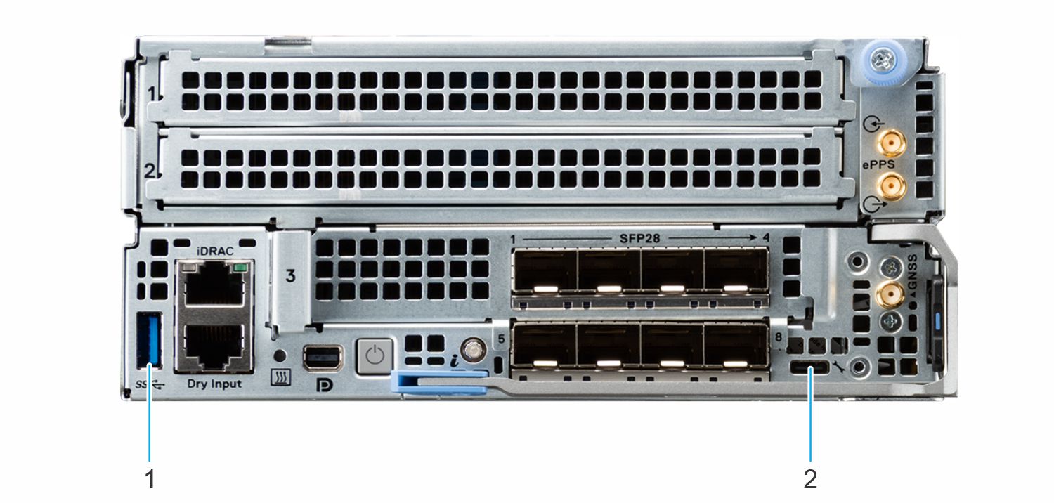
- USB 3.0 - A port
- USB- C port - iDRAC direct/Host port
iDRAC Direct Port
The iDRAC direct port is used for advanced server management and maintenance. This feature helps to directly connect device to the iDRAC Direct port. The iDRAC direct port is a USB-C connector and is located on the front I/O wall of the system. The iDRAC direct port can be switched between a host port and a management port by pressing the SID button for 5 s.
iDRAC port specifications
RJ45 Alert\Dry contact input connector
To enhance usage in IoT space, the XR8720t comes with dry input sensor. Each input are configurable and manageable in the iDRAC interface. These are interruptible inputs to iDRAC. Dry means no energy is supplied to the contacts. The dry contact connection cable with RJ45 connector on one end is custom to each installation and must be provided by the end user.
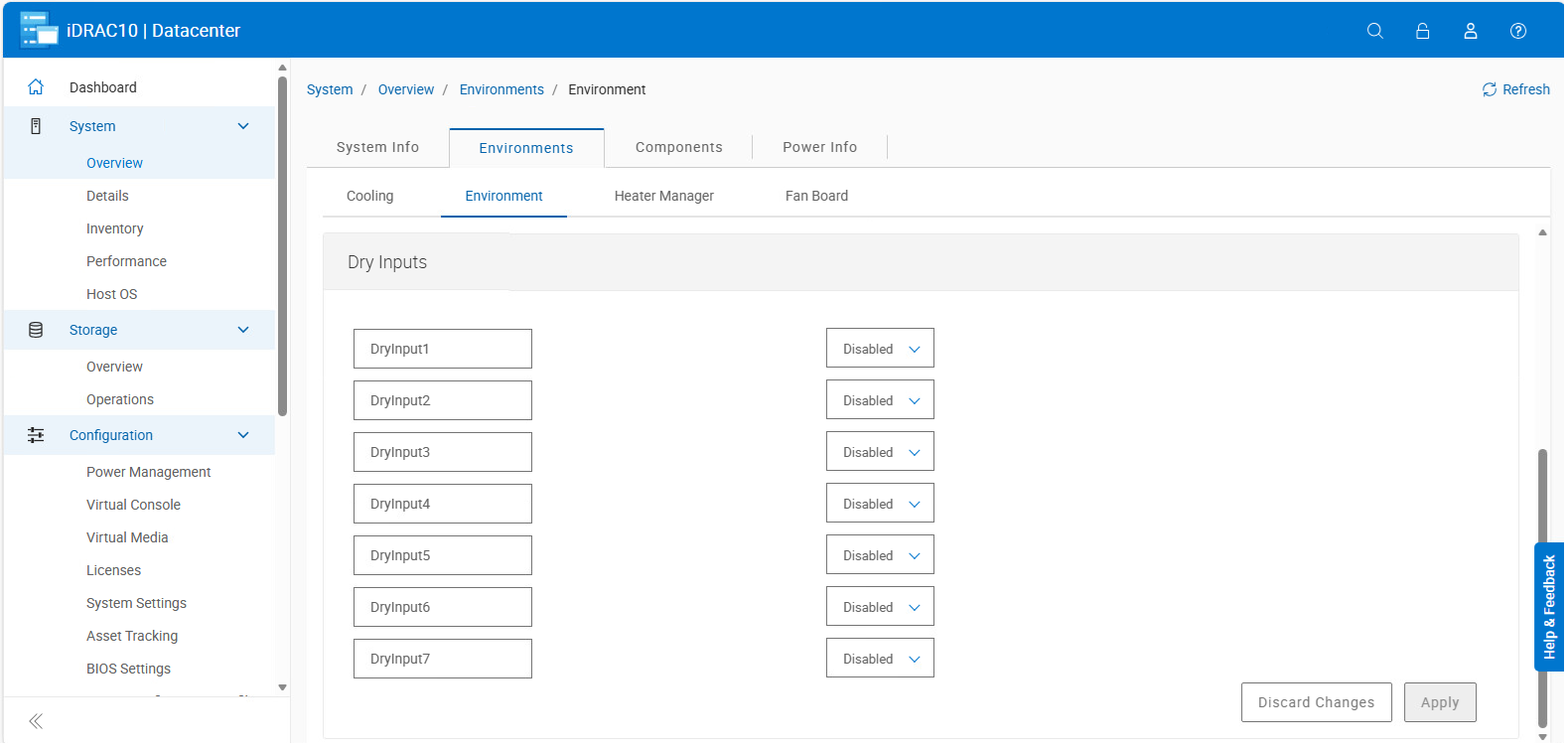
The default state of the dry inputs are off/disabled. User will have 7 (one for each dry input) enable/disable (default) control that must be enabled before logging will occur.
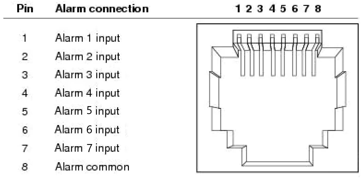
The 7 dry inputs are interruptible inputs to iDRAC. They have the following characteristics:
- Monitored by iDRAC for state transition and LC event will be logged for each state transition.
- NOT modeled as IPMI sensors but LC event only sensors. The current state of the input is not monitored or displayed anywhere.
- Event Log - transitions (Open to close or close to Open) will be logged in LC only.
Debounce — A debounce of 100ms is provided on all inputs.
| Message ID | Message | RRA | DD | Severity |
|---|---|---|---|---|
| DCI1000 | Dry input <input index> is transitioned to Open state. | None. | None | Severity -3 (Info) |
| DCI1001 | Dry input <input index> is transitioned to Close state. | None. | None | Severity -3 (Info) |
Display port
The PowerEdge XR8720t system supports one Mini-Display port video connector on the front of the system.
NIC port specifications
| Feature | Specifications |
|---|---|
| Flexible configuration | 2 x QSFP 100 Gbps ports |
| Network optimized configuration | 8 x SFP 10/25 Gbps ports |
| DSFF OCP Card | 8 x SFP 10/25 Gbps ports |
Video specifications
TThe PowerEdge XR8720t system supports integrated Matrox G200 graphics controller with 16 MB of video frame buffer.
| Resolution | Refresh Rate | Color depth (bits) |
|---|---|---|
| 1024 x 768 | 60 | 8, 16, 32 |
| 1280 x 800 | 60 | 8, 16, 32 |
| 1280 x 1024 | 60 | 8, 16, 32 |
| 1360 x 768 | 60 | 8, 16, 32 |
| 1440 x 900 | 60 | 8, 16, 32 |
| 1600 x 90 | 60 | 8, 16, 32 |
| 1600 x 1200 | 60 | 8, 16, 32 |
| 1680 x 1050 | 60 | 8, 16, 32 |
| 1920 x 1080 | 60 | 8, 16, 32 |
| 1920 x 1200 | 60 | 8, 16, 32 |
*(RB) - Reduced Blanking for Digital Displays requiring less blank time. It was introduced for Signal Integrity improvements by reducing Pixel Clock rates for VGA- Analog input devices.
Environmental specifications
| Temperature | Allowable continuous operations |
|---|---|
| Temperature range for altitudes <= 900 m (<= 2953 ft) | 10–35°C (50–95°F) with no direct sunlight on the equipment |
| Humidity percent range (non-condensing at all times) | 8% RH with -12°C minimum dew point to 80% RH with 21°C (69.8°F) maximum dew point |
| Operational altitude de-rating | Maximum temperature is reduced by 1°C/300 m (33.8°F/984 Ft) above 900 m (2953 Ft) |
| Temperature | Allowable continuous operations |
|---|---|
| Temperature range for altitudes <= 900 m (<= 2953 ft) | 5–40°C (41–104°F) with no direct sunlight on the equipment |
| Humidity percent range (non-condensing at all times) | 8% RH with -12°C minimum dew point to 85% RH with 24°C (75.2°F) maximum dew point |
| Operational altitude de-rating | Maximum temperature is reduced by 1°C/175 m (33.8°F/574 Ft) above 900 m (2953 Ft) |
| Temperature | Allowable continuous operations |
|---|---|
| Temperature range for altitudes <= 900 m (<= 2953 ft) | 5–45°C (41–113°F) with no direct sunlight on the equipment |
| Humidity percent range (non-condensing at all times) | 8% RH with -12°C minimum dew point to 90% RH with 24°C (75.2°F) maximum dew point |
| Operational altitude de-rating | Maximum temperature is reduced by 1°C/125 m (33.8°F/410 Ft) above 900 m (2953 Ft) |
| Temperature | Allowable continuous operations |
|---|---|
| Temperature range for altitudes <= 900 m (<= 2953 ft) | 5–55°C (41–131°F) with no direct sunlight on the equipment |
| Humidity percent range (non-condensing at all times) | 8% RH with -12°C minimum dew point to 90% RH with 24°C (75.2°F) maximum dew point |
| Operational altitude de-rating | Maximum temperature is reduced by 1°C/125 m (33.8°F/410 Ft) above 900 m (2953 Ft) |
| Temperature | Allowable continuous operations |
|---|---|
| Maximum temperature gradient (applies to both operation and non-operation) | 20°C in an hour* (36°F in an hour) and 5°C in 15 minutes (41°F in 15 minutes), 5°C in an hour* (41°F in an hour) for tape
NOTE:* - Per ASHRAE thermal guidelines for tape hardware, these are not instantaneous rates of temperature change.
|
| Non-operational temperature limits | -40 to 65°C (-104 to 149°F) |
| Non-operational humidity limits | 5% to 95% RH with 27°C (80.6°F) maximum dew point |
| Maximum non-operational altitude | 12,000 meters (39,370 feet) |
| Maximum operational altitude | 3,048 meters (10,000 feet) |
| Maximum vibration | Specifications |
|---|---|
| Operating | 0.26 Grms at 5 Hz to 350 Hz (all operation orientations) |
| Storage | 1.88 Grms at 10 Hz to 500 Hz for 15 minutes (all six sides tested) |
| Maximum shock pulse | Specifications |
|---|---|
| Operating | Six consecutively executed shock pulses in the positive and negative x, y, and z axis of 6 G for up to 11 ms. |
| Storage | Six consecutively executed shock pulses in the positive and negative x, y, and z axis (one pulse on each side of the system) of 71 G for up to 2 ms. |
Environmental Requirements for installing XR8000
The proper installation of the XR8000 chassis and associated sleds requires external-level protection of the system and its components from environmental conditions. The XR8000 unit is designed for expanded temperature range and resistance to seismic events. It is important to note that the unit is not a sealed unit.
General guidelines for maintaining the XR8000:
- It is recommended to keep the system from heat sources and obstructions blocking the airflow.
- It is recommended not to allow spillage of liquid into the system and not to operate when the system is wet.
- If there are any openings in the system, it is recommended not to insert any objects into those points.
- It is highly advised not to tamper with or modify PSUs as it could potentially damage the systems.
- DC power cables should be built according to the cabling instructions her: Cabling-instructions-for--48-to--60-DC-power-supply (dell.com)
Site Planning Recommendation:
- The site should have proper cooling facilities to take care of the operating temperature range of the server.
- The rack or cabinet where the server is going to be installed should have adequate space for cable routing.
- The Rack or cabinet should have enough strength to hold the weight of the server.
- For Conductive dust, the air must be free of conductive dust, zinc whiskers, or other conductive particles. This protects the system from any contamination. This can be accomplished by sufficient air filtration at the ingress to the cabinet.
- For corrosive dust, the air must be free from any corrosive dust and the Residual dust present in the air must have a deliquescent point less than 60% relative humidity.
- The system is best found to operate at -5C to 55C and for some conditions from -20C to 65C. The cabinet could maintain this optimum operating range.
- For protection of the system from humidity it is expected to have an environment with a humidity percent range of 8% RH with -12°C minimum dew point to 80% RH with 21°C (69.8°F) maximum dew point.
- For seismic zones, the XR8000 and XR8720t/XR8620t/XR8610t sleds are rated to support seismic conditions per the NEBS GR-63 spec. Dell standard rails for the system are also rated for the seismic conditions. Note this assumes the rack that the unit is installed in is rated for seismic conditions. It also assumes that the cabinet and other components in the cabinet are rated for seismic conditions.
Environmental considerations
The PowerEdge system is targeted for edge deployments and it meets all the additional standards for thermal, shock, and vibration parameters.
| Industry | Configuration | Description |
|---|---|---|
| Telco | GR-1089-CORE | Electromagnetic Compatibility and Electrical Safety – Generic Criteria for Network Telecommunications Equipment |
| GR-63-CORE | NEBS Requirements: Physical Protection | |
| SR-3580 (NEBS Level 3) | NEBS Criteria Levels | |
| GR-3108-CORE (Class 1) | Network Equipment in the Outside Plant (OSP). An exception is made for cold boot at +5C instead of -5C for systems without the Heater Manager subsystem enabled. | |
| Military | N/A | |
| Marine | N/A | |
| Power Industry | N/A | |
| Safety | N/A | LDV, IEC/EN, CFR, CSA |
| EMC | N/A | EN, CISPR, ES, DTAG, CFR, ICES, VCCI |
| EMV | N/A | RoHS, WEEE, EN, ECE |
Environmental Requirements for installing XR8000
A proper installation of XR8000 protects the system and its components from damage that is caused by external environmental conditions. So, to ensure normal operation and avoid any unplanned downtime and maintenance activity it is highly imperative that there is a proper planning and preparation of the site before installing the XR8000 . Also, it is to be noted that the same site sanity must be maintained during the entire life cycle of the XR8000 server to ensure smooth operations.
General guidelines for maintaining the XR8000:
- It is recommended to keep the system from heat sources and obstructions blocking the airflow.
- It is recommended not to allow spillage of liquid into the system and not to operate when the system is wet.
- If there are any openings in the system, it is recommended not to insert any objects into those points.
- It is highly advised not to tamper and modify any power cables or PSUs as it could potentially damage the systems.
Site Planning Recommendation:
- The site should have proper cooling facilities to take care of the operating temperature range of the server.
- The rack or cabinet where the server is going to be installed should have adequate space for cable routing.
- The Rack or cabinet should have enough strength to hold the weight of the server.
- For Conductive dust, the air must be free of conductive dust, zinc whiskers, or other conductive particles. This protects the system from any contamination.
- For corrosive dust, the air must be free from any corrosive dust and the Residual dust present in the air must have a deliquescent point less than 60% relative humidity. Note this condition applies for both data center and non-data center environments.
- The system is best found to operate at -5C to 55C and for some conditions from -20C to 65C , so the site conditions could maintain the optimum operating condition.
- For protection of the system from humidity it is expected to have an environment with a humidity percent range of 8% RH with -12°C minimum dew point to 80% RH with 21°C (69.8°F) maximum dew point.
- For seismic zones , the maximum operating vibration is 0.21 G rms at 5 Hz to 500 Hz (all operation orientations).
Thermal air restrictions
Fresh air environment
- Two PSUs are required in redundant mode, however a single PSU failure is not supported.
- PCIeSSD is not supported.
- 128 GB or greater capacity DIMMs are not supported.
- GPU and FPGA are not supported.
- CPU TDP equal or greater than 180 W are not supported.
- Rear drives are not supported.
- Non-Dell qualified peripheral cards and/or peripheral cards greater than 25 W are not supported.
| ASHRAE | A3/40°C (104°F) | A4/45°C (113°F) |
|---|---|---|
| PSU | Two PSUs are required in redundant mode. If there is a PSU failure, system performance may be reduced. | |
| PCIe card | Non-Dell qualified peripheral cards and peripheral cards greater than 25 W are not supported. | |
| GPU/FPGA | Not supported | |
| DIMM | 128 GB, or greater capacity DIMMs are not supported. | |
| PCIe SSD | Not supported | |
| Front storage | Not supported in 12 x 3.5-inch SAS configuration. | |
| Rear storage | Not supported | |
| Fan | HPR SLVR fans are required. | |
| Processor | ≤ 165 W | ≤ 125 W |
| OCP | Supported with 85°C (185°F) active optic cable. | Supported with 85°C (185°F) active optic cable and cards tier ≤4. |
| BOSS | BOSS-N1 is supported. | BOS-N1 is not supported. |
| ASHRAE | A3/40°C (104°F) | A4/45°C (113°F) |
|---|---|---|
| PSU | Two PSUs are required in redundant mode. If there is a PSU failure, system performance may be reduced. | |
| PCIe card | Non-Dell qualified peripheral cards and peripheral cards greater than 25 W are not supported. | |
| GPU/FPGA | Not supported | |
| DIMM | 128 GB, or greater capacity DIMMs are not supported. | |
| PCIe SSD | Not supported | |
| Front storage | Not supported in 12 x 3.5-inch SAS configuration. | |
| Rear storage | Not supported | |
| Fan | HPR SLVR fans are required in 2.5-inch configurations systems. | |
| OCP | Supported with 85°C (185°F) active optic cable. | Supported with 85°C (185°F) active optic cable and cards tier ≤4. |
| BOSS | BOSS-N1 is supported. | BOSS-N1 is not supported. |
Particulate and gaseous contamination specifications
The following table defines the limitations that help avoid any equipment damage or failure from particulates and gaseous contamination. If the levels of particulates or gaseous pollution exceed the specified limitations and result in equipment damage or failure, you must rectify the environmental conditions. Remediation of environmental conditions is the responsibility of the customer.
| Particulate contamination | Specifications |
|---|---|
| Air filtration: Conventional Data Center only | Data center air filtration as defined by ISO Class 8 per ISO 14644-1 with a 95% upper confidence limit
NOTE: Filtering room air with a MERV8 filter, as specified in ANSI/ASHRAE Standard 127, is a recommended method for achieving the necessary environmental conditions.
NOTE:Air entering the data center must have MERV11 or MERV13 filtration.
NOTE:This condition applies to data center environments only. Air filtration requirements do not apply to IT equipment designed to be used outside a data center, in environments such as an office or factory floor.
|
| Walk-Up Edge Data Center or Cabinet (sealed, closed loop environment) | Filtration is not required for cabinets that are anticipated to be opened six times or less per year. Class 8 per ISO 1466-1 filtration as defined above is required otherwise.
NOTE: In environments commonly above ISA-71 Class G1 or that may have known challenges, special filters may be required.
|
| Conductive dust: data center and non-data center environments | Air must be free of conductive dust, zinc whiskers, or other conductive particles.
NOTE: Conductive dust, which can interfere with equipment operation, can originate from various sources, including manufacturing processes and zinc whiskers that may develop on the plating of raised floor tiles.
NOTE:This condition applies to data center and non-data center environments.
|
| Corrosive dust: data center and non-data center environments |
NOTE:This condition applies to data center and non-data center environments.
|
| Gaseous contamination | Specifications | Notes |
|---|---|---|
| Copper coupon corrosion rate | ISA-71 Class G1: <300 Å/month | Per ANSI/ISA71.04 |
| Silver coupon corrosion rate | ISA-71 Class G1: <200 Å/month | Per ANSI/ISA71.04 |