




























Sled dimensions
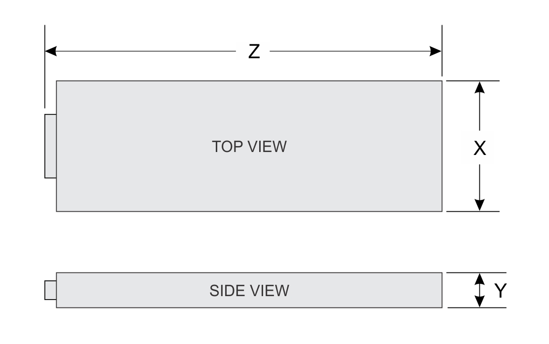
| X | Y | Z (handle closed) |
|---|---|---|
| 184.8 mm (7.27 inches) | 41.25 (1.62 inches) | 433.5 mm (17.06 inches) |
System weight
| System configuration | Maximum weight (with all SSDs) |
|---|---|
| 8 x DIMMS, 1 x processor, 2 x 2280 M.2 NVMe SSDs on BOSS-N1 card | 3.90 kg (8.59 lb) |
Processor specifications
| Supported processor | Number of processors supported |
|---|---|
| 5th Generation Intel Xeon Scalable and Edge-Enhanced processors with up to 16 cores or 4th Generation Intel Xeon Scalable and Edge-Enhanced processors with up to 32 cores | One |
Cooling fan specifications
Supported operating systems
The PowerEdge XR8610t system supports the following operating systems:
- Red Hat Enterprise Linux
- SUSE Linux Enterprise Linux
- VMware ESXi
- WindRiver Solution
- Dell NativeEdge OS
For more information, go to OS support.
System battery specifications
The PowerEdge XR8610t system supports CR 2032 3.0-V lithium coin cell system battery.
Memory specifications
| DIMM type | DIMM rank | DIMM capacity | Single processor | |
|---|---|---|---|---|
| Minimum RAM | Maximum RAM | |||
| RDIMM | Single rank | 16 GB | 32 GB | 128 GB |
| Dual rank | 32 GB | 64 GB | 256 GB | |
| Dual rank | 64 GB | 128 GB | 512 GB | |
| Dual rank | 96 GB | 192 GB | 768 GB | |
| Memory module sockets | Speed |
|---|---|
| 8, 288-pin | 6400 MT/s, 5600 MT/s, 4800 MT/s |
Expansion card riser specifications
| PCIe slots | Expansion card riser | Processor connection | Height | Length | Slot width |
|---|---|---|---|---|---|
| Slot 1 | R2A | Processor 1 | Full Height | Half Length | x16 PCIe (Gen5) Single width |
Drives
USB ports specifications
| Front | |
|---|---|
| USB port type | No. of ports |
| USB 3.0-compliant port | One |
| iDRAC Direct port (Micro-AB USB 2.0-compliant port) | One |
Network port specifications
| Feature | Specifications |
|---|---|
| LOM | 2 x 25 GbE SFP 28 LOM connectors (optional). |
Serial connector specifications
The PowerEdge XR8610t system supports one Micro USB Type B serial connector, on front of the system.
Display port
The PowerEdge XR8610t system supports One Mini-DisplayPort on front of the system.
iDRAC port specifications
RJ-45 dry contact port
To enhance usage in the IoT space, the XR8610t comes with a dry input sensor. Each input is configurable and manageable in the iDRAC interface. These are interruptible inputs to iDRAC. Dry means that no energy is supplied to the contacts. The dry contact connection cable with RJ45 connector on one end is custom to each installation and must be provided by the end user.
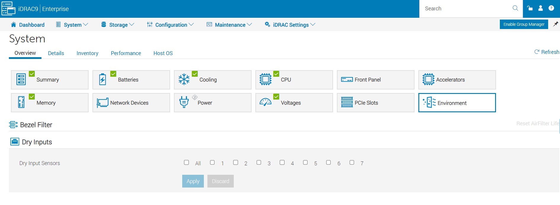
The default states of the dry inputs are off/disabled. The user has seven (one for each dry input) enable/disable (default) control that must be enabled before logging occurs.
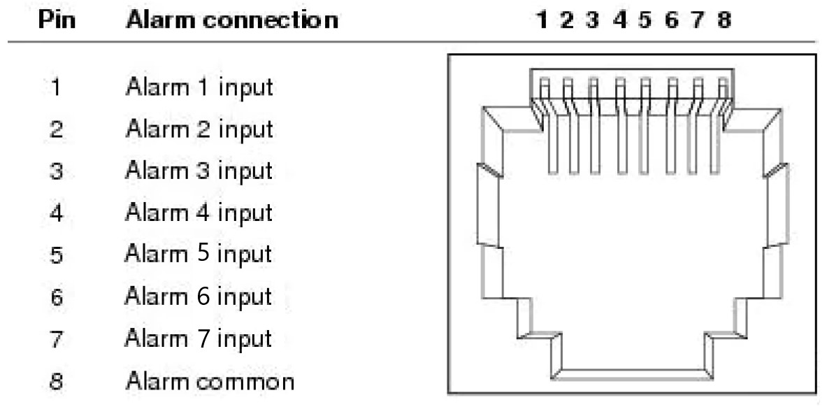
The seven dry inputs are interruptible inputs to iDRAC. They have the following characteristics:
- Monitored by iDRAC for state transition and LC event are for each state transition.
- NOT modeled as IPMI sensors but LC event only sensors. The current state of the input is not monitored or displayed anywhere.
- Event log - transitions (Open to close or close to Open) are logged in LC only.
Debounce — A debounce of 100mseconds is provided on all inputs.
| Message ID | Message | RRA | DD | Severity |
|---|---|---|---|---|
| DCI1000 | Dry input <input index> is transitioned to Open state. | None. | None | Severity -3 (Info) |
| DCI1001 | Dry input <input index> is transitioned to Close state. | None. | None | Severity -3 (Info) |
Video specifications
| Resolution | Refresh rate (Hz) | Color depth (bits) |
|---|---|---|
| 640 x 480 | 60 | 8, 16, 32 |
| 800 x 600 | 60 | 8, 16, 32 |
| 1024 x 768 | 60 | 8, 16, 32 |
| 1152 x 864 | 60 | 8, 16, 32 |
| 1280 x 800 | 60 | 8, 16, 32 |
| 1280 x 1024 | 60 | 8, 16, 32 |
| 1360 x 768 | 60 | 8, 16, 32 |
| 1400 x 1050 | 60 | 8, 16, 32 |
| 1440 x 900 | 60 | 8, 16, 32 |
| 1600 x 1200 | 60 | 8, 16, 32 |
| 1680 x 1050 | 60 | 8, 16, 32 |
| 1920 x 1080 | 60 | 8, 16, 32 |
| 1920 x 1200 | 60 | 8, 16, 32 |
Environmental specifications
| Feature | Allowable continuous operations |
|---|---|
| Temperature range for altitudes <= 900 m (<= 2953 ft) | 10–35°C (50–95°F) with no direct sunlight on the equipment |
| Humidity percent range (non-condensing at all times) | 8% RH with -12°C minimum dew point to 80% RH with 21°C (69.8°F) maximum dew point |
| Operational altitude de-rating | Maximum temperature is reduced by 1°C/300 m (1.8°F/984 Ft) above 900 m (2953 Ft) |
| Feature | Allowable continuous operations |
|---|---|
| Temperature range for altitudes <= 900 m (<= 2953 ft) | -5° to 55°C (23 to 131°F) with no direct sunlight on the equipment |
| Humidity percent range (non-condensing at all times) | 8% RH with -12°C minimum dew point to 90% RH with 24°C (75.2°F) maximum dew point |
| Operational altitude de-rating | Maximum temperature is reduced by 1°C/80 m (1.8°F/263 Ft) above 900 m (2953 Ft) |
| Feature | Allowable continuous operations |
|---|---|
| Maximum temperature gradient (applies to both operation and non-operation). | 20°C in an hour* (36°F in an hour) and 5°C in 15 minutes (9°F in 15 minutes), 5°C in an hour* (9°F in an hour) for tape hardware |
| Non-operational temperature limits | -40 to 65°C (-40 to 149°F). |
| Non-operational humidity limits (Non-Condensing at all times) | 5% to 95%RH with 27°C (80.6°F) maximum dew point |
| Maximum non-operational altitude | 12,000 meters (39,370 feet) |
| Maximum operational altitude | 3,050 meters (10,006 feet) |
| Maximum vibration | Specifications |
|---|---|
| Operating | 0.21 Grms at 5 Hz to 500 Hz (all operation orientations) |
| Storage | 1.88 Grms at 10 Hz to 500 Hz for 15 minutes (all six sides tested) |
| Maximum shock pulse | Specifications |
|---|---|
| Operating | Six consecutively executed shock pulses in the positive and negative x, y, and z axis of 6 G for up to 11 ms (4 pulse on each side on the system) |
| Storage | Six consecutively executed shock pulses in the positive and negative x, y, and z axis (one pulse on each side of the system) of 71 G for up to 2 ms |
Particulate and gaseous contamination specifications
The following table defines the limitations that help avoid any equipment damage or failure from particulates and gaseous contamination. If the levels of particulates or gaseous pollution exceed the specified limitations and result in equipment damage or failure, you may need to rectify the environmental conditions. Remediation of environmental conditions is the responsibility of the customer.| Particulate contamination | Specifications |
|---|---|
| Conductive dust | Air must be free of conductive dust, zinc whiskers, or other conductive particles.
NOTE:This condition applies to data center and non-data center environments.
|
| Corrosive dust |
NOTE:This condition applies to data center and non-data center environments.
|
| Gaseous contamination | Specifications |
|---|---|
| Copper coupon corrosion rate | <300 Å/month per Class G1 as defined by ANSI/ISA71.04-2013 |
| Silver coupon corrosion rate | <200 Å/month as defined by ANSI/ISA71.04-2013 |
Environmental considerations
The PowerEdge system is targeted for edge deployments and it meets all the additional standards for thermal, shock, vibration parameters.
| Industry | Configuration | Description |
|---|---|---|
| Telco | GR-1089-CORE | Electromagnetic Compatibility and Electrical Safety – Generic Criteria for Network Telecommunications Equipment |
| GR-63-CORE | NEBS Requirements: Physical Protection | |
| SR-3580 (NEBS Level 3) | NEBS Criteria Levels | |
| GR-3108-CORE (Class 1) | Network Equipment in the Outside Plant (OSP). An exception is made for cold boot at +5C instead of -5C for systems without the heater subsystem enabled. | |
| Military | N/A | |
| Marine | N/A | |
| Power Industry | N/A | |
| Safety | N/A | LDV, IEC/EN, CFR, CSA |
| EMC | N/A | EN, CISPR, ES, DTAG, CFR, ICES, VCCI |
| EMV | N/A | RoHS, WEEE, EN, ECE |
Particulate and gaseous contamination specifications
The following table defines the limitations that help avoid any equipment damage or failure from particulates and gaseous contamination. If the levels of particulates or gaseous pollution exceed the specified limitations and result in equipment damage or failure, you must rectify the environmental conditions. Remediation of environmental conditions is the responsibility of the customer.
| Particulate contamination | Specifications |
|---|---|
| Air filtration: Conventional Data Center only | Data center air filtration as defined by ISO Class 8 per ISO 14644-1 with a 95% upper confidence limit
NOTE: Filtering room air with a MERV8 filter, as specified in ANSI/ASHRAE Standard 127, is a recommended method for achieving the necessary environmental conditions.
NOTE:Air entering the data center must have MERV11 or MERV13 filtration.
NOTE:This condition applies to data center environments only. Air filtration requirements do not apply to IT equipment designed to be used outside a data center, in environments such as an office or factory floor.
|
| Walk-Up Edge Data Center or Cabinet (sealed, closed loop environment) | Filtration is not required for cabinets that are anticipated to be opened six times or less per year. Class 8 per ISO 1466-1 filtration as defined above is required otherwise.
NOTE: In environments commonly above ISA-71 Class G1 or that may have known challenges, special filters may be required.
|
| Conductive dust: data center and non-data center environments | Air must be free of conductive dust, zinc whiskers, or other conductive particles.
NOTE: Conductive dust, which can interfere with equipment operation, can originate from various sources, including manufacturing processes and zinc whiskers that may develop on the plating of raised floor tiles.
NOTE:This condition applies to data center and non-data center environments.
|
| Corrosive dust: data center and non-data center environments |
NOTE:This condition applies to data center and non-data center environments.
|
| Gaseous contamination | Specifications | Notes |
|---|---|---|
| Copper coupon corrosion rate | ISA-71 Class G1: <300 Å/month | Per ANSI/ISA71.04 |
| Silver coupon corrosion rate | ISA-71 Class G1: <200 Å/month | Per ANSI/ISA71.04 |
Thermal restriction matrix
| Config | Thermal Restriction | |||
|---|---|---|---|---|
| Ambient Temperature | ASHARE A2 (Max 35°C) | NEBS3 (Max 55°C) | ||
| CPU | Intel® Xeon® Gold 4514Y | 150 W | Supported | Supported |
| CPU | Intel® Xeon® Gold 6433N | 205 W | Supported | Supported |
| Intel® Xeon® Gold 6423N | 195 W | Supported | Supported | |
| Intel® Xeon® Gold 6403N | 185 W | Supported | Supported | |
| Intel® Xeon® Gold 4510 | 150 W | Supported | Supported | |
| Intel® Xeon® Gold 5423N | 145 W | Supported | Supported | |
| Intel® Xeon® Gold 4509Y | 125 W | Supported | Supported | |
| CPU | Intel® Xeon® Gold 6438N | 205 W | Supported | Supported |
| Intel® Xeon® Gold 6421N | 185 W | Supported | Supported | |
| Intel® Xeon® Gold 5411N | 165 W | Supported | Supported | |
| Memory | DDR5 RDIMM 4800 MT/s 64G | Supported | Supported | |
| DDR5 RDIMM 4800 MT/s 32G | Supported | Supported | ||
| DDR5 RDIMM 4800 MT/s 16G | Supported | Supported | ||
| DDR5 RDIMM 5600 MT/s 96G | Supported | Supported | ||
| DDR5 RDIMM 5600 MT/s 64G | Supported | Supported | ||
| DDR5 RDIMM 5600 MT/s 32G | Supported | Supported | ||
| DDR5 RDIMM 5600 MT/s 16G | Supported | Supported | ||
| Sled Config | XR8620t Thermal Restriction | ||||
|---|---|---|---|---|---|
| Ambient Temperature | ASHRAE A2
(Max 35°C) |
NEBS3
(Max 55°C) |
|||
| BOSS-N1 | Hynix M.2 | 480G | PE8010 2280 | Supported | Supported |
| 480G | PE9010 2280 | Supported | Supported | ||
| 800G | PE8030 2280 | Supported | Supported | ||
| 960G | PE8010 2280 | Supported | Supported | ||
| 960G | PE9010 2280 | Supported | Supported | ||
| 1.92T | PE9010 2280 | Supported | Supported | ||
| Micron M.2 | 480G | 7400 2280 | Supported | Supported | |
| 480G | 7450 2280 | Supported | Supported | ||
| 800G | 7400 2280 | Supported | Supported | ||
| 960G | 7400 2280 | Supported | Supported | ||
| 960G | 7450 2280 | Supported | Supported | ||
| Sled Config | XR8620t Thermal Restriction | ||||
|---|---|---|---|---|---|
| Ambient Temperature | ASHRAE A2
(Max 35°C) |
NEBS3
(Max 55°C) |
|||
| Dual M.2 riser | Hynix M.2 | 480G | PE8010 2280 | Supported | Supported |
| 800G | PE8030 2280 | Supported | Supported | ||
| 960G | PE8010 2280 | Supported | Supported | ||
| 1.92T | PE8110 22110 | Supported | Supported | ||
| 3.84T | PE8110 22110 | Supported | Supported | ||
| Micron M.2 | 480G | 7400 2280 | Supported | Supported | |
| 800G | 7400 2280 | Supported | Supported | ||
| 960G | 7400 2280 | Supported | Supported | ||
| 960G | 7450 2280 | Supported | Supported | ||
| 1.92T | 7400 22110 | Supported | Supported | ||
| 1.92T | 7450 22110 | Supported | Supported | ||
| 3.84T | 7400 22110 | Supported | Supported | ||
| 3.84T | 7450 22110 | Supported | Supported | ||
| Sled Config | XR8620t Thermal Restriction | ||||
|---|---|---|---|---|---|
| Ambient Temperature | ASHRAE A2
(Max 35°C) |
NEBS3
(Max 55°C) |
|||
| Dual M.2 riser + Single M.2 riser | Hynix M.2 | 480G | PE8010 2280 | Supported | Supported |
| 800G | PE8030 2280 | Supported | Supported | ||
| 960G | PE8010 2280 | Supported | Supported | ||
| 1.92T | PE8110 22110 | Supported | Supported | ||
| 3.84T | PE8110 22110 | Supported | Supported | ||
| Micron M.2 | 480G | 7400 2280 | Supported | Supported | |
| 800G | 7400 2280 | Supported | Supported | ||
| 960G | 7400 2280 | Supported | Supported | ||
| 960G | 7450 2280 | Supported | Supported | ||
| 1.92T | 7400 22110 | Supported | Not supported | ||
| 1.92T | 7450 22110 | Supported | Supported | ||
| 3.84T | 7400 22110 | Supported | Not supported | ||
| 3.84T | 7450 22110 | Supported | Supported | ||
| Sled Config | XR8620t Thermal Restriction | ||||
|---|---|---|---|---|---|
| Ambient Temperature | ASHRAE A2
(Max 35°C) |
NEBS3
(Max 55°C) |
|||
| BOSS-N1 + Single M.2 riser | Hynix M.2 | 480G | PE8010 2280 | Supported | Supported |
| 800G | PE8030 2280 | Supported | Supported | ||
| 960G | PE8010 2280 | Supported | Supported | ||
| Micron M.2 | 480G | 7400 2280 | Supported | Supported | |
| 800G | 7400 2280 | Supported | Supported | ||
| 960G | 7400 2280 | Supported | Supported | ||
| 960G | 7450 2280 | Supported | Supported | ||
| Config | Thermal Restriction | |||
|---|---|---|---|---|
| Ambient Temperature | ASHARE A2 (Max 35°C) | NEBS3 (Max 55°C) | ||
| PCIe Card | Non-Dell PCIe cards are not supported. | |||
| PSU | Dual PSUs are required for NEBS3 | |||
| Sled Config | XR8620t Thermal Restriction | |||
|---|---|---|---|---|
| Ambient Temperature | ASHRAE A2
(Max 35°C) |
NEBS3
(Max 55°C) |
||
| Qualcomm X100 DPU | Supported | Supported | ||
| Nokia Rinline 2 DPU | Supported | Supported | ||
| Minerva 3 DPU | Supported | Supported | ||
XR8610t- Other Restrictions
- Hot-swap fans are not supported.
- Minimum cold boot temperature +5°C.
- Do not perform a cold startup below 5°C.
- DIMM Blank is required in empty slots.
- Sled blank is required in empty slots.
- PCIE blank is required in the empty slot (slot 1).
- PSU blank is required in empty slots.
- Air baffle is required while single M.2 riser is not installed.