




























Chassis dimensions
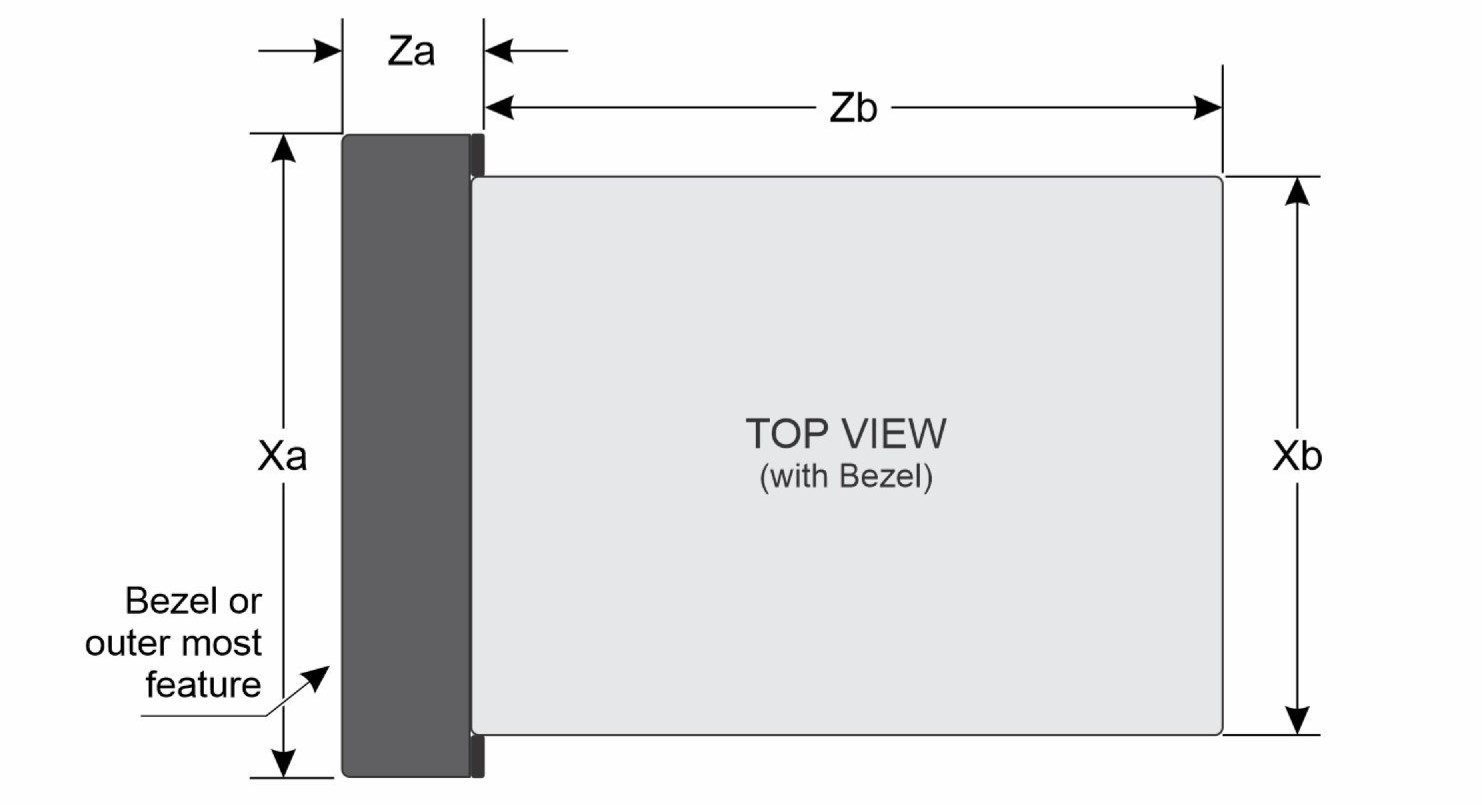
| Xa | Xb | Y | Za | Zb |
|---|---|---|---|---|
| 482.6 mm (19 inches) | 448 mm (17.63 inches) | 87.05 mm (3.42 inches) | 102 mm (4.01 inches) with bezel | 430 mm (16.92 inches) |
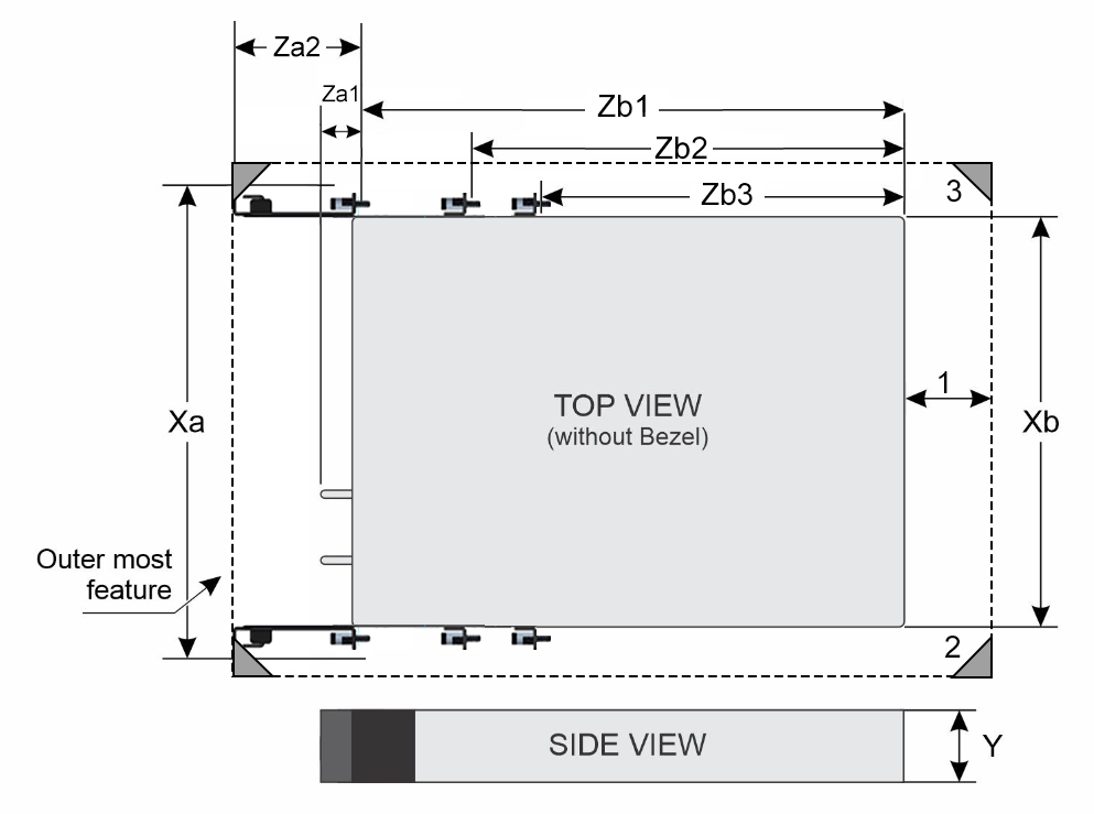
| Xa | Xb | Y | Za1 | Za2 | Zb1 | Zb2 | Zb3 |
|---|---|---|---|---|---|---|---|
| 482 mm (18.97 inches) includes rack mount ear. | 448 mm (17.63 inches) | 87.05 mm (3.42 inches) | 30.4 mm (1.19 inches) without bezel | 89 mm (3.50 inches) with cable management kit included | 423 mm (16.65 inches) | 343 mm (13.50 inches) | 293 mm (11.53 inches) |
- Minimum exhaust gap (between chassis rear and cabinet’s rear door) required for thermal performance:
- 50 mm minimum for ambient temperatures up to 55°C
- 55 mm minimum for ambient temperatures 55 - 65°C
- Four post rack.
- 19-inch or 23-inch width cabinet boundary and 600 mm (23.62 inches) minimum cabinet depth.
System weight
| System configuration | Maximum weight (with all drives/SSDs) |
|---|---|
| Weight of chassis without sleds | 5.82 kg (12.8 pounds) |
| Weight of chassis with two XR8620t sleds | 18.52 kg (40.84 pounds) |
| Chassis weight | Description |
|---|---|
| 40 pounds - 70 pounds | Recommend two persons to lift. |
| 70 pounds- 120 pounds | Recommend three persons to lift. |
| ≥ 121 pounds | Recommend to use a server-lift. |
PSU specifications
The PowerEdge XR8000r system supports up to two AC or DC power supply units (PSUs).
| PSU | Class | Heat dissipation (maximum) (BTU/hr) | Frequency (Hz) | Voltage | AC | DC | Current (A) | |
|---|---|---|---|---|---|---|---|---|
| High line 200–240 V | Low line 100–120 V | |||||||
| 1800 W Mixed Mode | Titanium | 6750 BTU/hr | 50/60 Hz | 200–240 V AC | 1800 W | N/A | N/A | 10 A |
| 6750 BTU/hr | N/A | 240 V DC | N/A | N/A | 1800 W | 8.2 A | ||
| 1400 W Mixed Mode | Platinum | 5250 BTU/hr | 50/60 Hz | 100–240 V AC | 1400 W | 1050 W | N/A | 12 A - 8 A |
| 5250 BTU/hr | N/A | 240 V DC | N/A | N/A | 1400 W | 6.6 A | ||
| 1400 W DC | N/A | 5310 BTU/hr | N/A | -48—( -60) V | N/A | N/A | 1400 W | 33.5 A |
| 1100 W DC | N/A | 4265 BTU/hr | N/A | -48—( -60) V | N/A | N/A | 1100 W | 27 A |
| 800 W DC | N/A | 3219 BTU/hr | N/A | -48—( -60) V | N/A | N/A | 800 W | 20 A |
Power module assembly
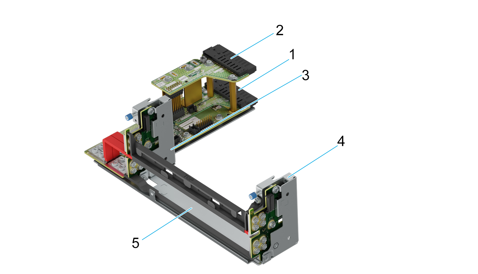
The Dell PowerEdge XR8000r has a power module assembly which consists of two power distribution boards (PDBs) and are connected to each other so either or both power supplies can power the whole chassis. The power distribution board (PDB) at the bottom also has chassis manager board to manage the chassis.
| Item | Component | Description |
|---|---|---|
| 1 | Power distribution board 2/ Chassis Manager (PDB2/CM) | This is the power distribution board which provides power to the chassis components. The PSU 2 slot is on the PDB 2. Chassis Manager (CM) is also integrated on this board. |
| 2 | Power distribution board 1 (PDB1) | This is the power distribution board which provides power to the chassis components. The PSU 1 slot is on the PDB 1. |
| 3 | Power Interposer Board (PIB) | The power interposer board (PIB) provides power to the 1U and 2U sleds. |
| 4 | Power Interposer Board (PIB) | The power interposer board (PIB) provides power to the 1U and 2U sleds. |
| 5 | Power module tray | The power module tray houses the complete power module assembly. |
PowerEdge XR8610t
| Connector | Description |
|---|---|
| USB ports and connectors |
|
PowerEdge XR8620t
| Ports and connectors | |
|---|---|
|
Environmental specifications
| Feature | Allowable continuous operations |
|---|---|
| Temperature range for altitudes <= 900 m (<= 2953 ft) | 10–35°C (50–95°F) with no direct sunlight on the equipment |
| Humidity percent range (non-condensing at all times) | 8% RH with -12°C minimum dew point to 80% RH with 21°C (69.8°F) maximum dew point |
| Operational altitude de-rating | Maximum temperature is reduced by 1°C/300 m (1.8°F/984 Ft) above 900 m (2953 Ft) |
| Feature | Allowable continuous operations |
|---|---|
| Temperature range for altitudes <= 900 m (<= 2953 ft) | -5° to 55°C (23 to 131°F) with no direct sunlight on the equipment |
| Humidity percent range (non-condensing at all times) | 8% RH with -12°C minimum dew point to 90% RH with 24°C (75.2°F) maximum dew point |
| Operational altitude de-rating | Maximum temperature is reduced by 1°C/80 m (1.8°F/263 Ft) above 900 m (2953 Ft) |
| Feature | Allowable continuous operations |
|---|---|
| Temperature range for altitudes <= 900 m (<= 2953 ft) | -20° to 65°C (-4 to 149°F) with no direct sunlight on the equipment. Cold boot support at - 20°C |
| Humidity percent range (non-condensing at all times) | 8% RH with -12°C minimum dew point to 90% RH with 24°C (75.2°F) maximum dew point |
| Operational altitude de-rating | Maximum temperature is reduced by 1°C/58 m (1.8°F/190 Ft) above 900 m (2953 Ft) |
| Feature | Allowable continuous operations |
|---|---|
| Temperature range for altitudes <= 900 m (<= 2953 ft) | -20° to 55°C (-4 to 131°F) with no direct sunlight on the equipment. Cold boot support at - 20°C |
| Humidity percent range (non-condensing at all times) | 8% RH with -12°C minimum dew point to 90% RH with 24°C (75.2°F) maximum dew point |
| Operational altitude de-rating | Maximum temperature is reduced by 1°C/80 m (1.8°F/263 Ft) above 900 m (2953 Ft) |
| Feature | Allowable continuous operations |
|---|---|
| Temperature range for altitudes <= 900 m (<= 2953 ft) | -5° to 65°C (23 to 149°F) with no direct sunlight on the equipment |
| Humidity percent range (non-condensing at all times) | 8% RH with -12°C minimum dew point to 90% RH with 24°C (75.2°F) maximum dew point |
| Operational altitude de-rating | Maximum temperature is reduced by 1°C/58 m (1.8°F/190 Ft) above 900 m (2953 Ft) |
| Feature | Allowable continuous operations |
|---|---|
| Maximum temperature gradient (applies to both operation and non-operation). | 20°C in an hour* (36°F in an hour) and 5°C in 15 minutes (9°F in 15 minutes), 5°C in an hour* (9°F in an hour) for tape hardware |
| Non-operational temperature limits | -40°C to 65°C (-40°F to 149°F). |
| Non-operational humidity limits (Non-Condensing at all times) | 5% to 95%RH with 27°C (80.6°F) maximum dew point |
| Maximum non-operational altitude | 12,000 meters (39,370 feet) |
| Maximum operational altitude | 3,050 meters (10,006 feet) |
| Maximum vibration | Specifications |
|---|---|
| Operating | 0.21 Grms at 5 Hz to 500 Hz (all operation orientations) |
| Storage | 1.88 Grms at 10 Hz to 500 Hz for 15 minutes (all six sides tested) |
| Maximum shock pulse | Specifications |
|---|---|
| Operating | Six consecutively performed shock pulses in the positive and negative x, y, and z axis of 6 G for up to 11 ms (4 pulse on each side on the system) |
| Storage | Six consecutively performed shock pulses in the positive and negative x, y, and z axis (one pulse on each side of the system) of 71 G for up to 2 ms |
Particulate and gaseous contamination specifications
The following table defines the limitations that help avoid any equipment damage or failure from particulates and gaseous contamination. If the levels of particulates or gaseous pollution exceed the specified limitations and result in equipment damage or failure, you may need to rectify the environmental conditions. Remediation of environmental conditions is the responsibility of the customer.| Particulate contamination | Specifications |
|---|---|
| Conductive dust | Air must be free of conductive dust, zinc whiskers, or other conductive particles.
NOTE:This condition applies to data center and non-data center environments.
|
| Corrosive dust |
NOTE:This condition applies to data center and non-data center environments.
|
| Gaseous contamination | Specifications |
|---|---|
| Copper coupon corrosion rate | <300 Å/month per Class G1 as defined by ANSI/ISA71.04-2013 |
| Silver coupon corrosion rate | <200 Å/month as defined by ANSI/ISA71.04-2013 |
Environmental considerations
The PowerEdge system is targeted for edge deployments and it meets all the additional standards for thermal, shock, and vibration parameters.
| Industry | Configuration | Description |
|---|---|---|
| Telco | GR-1089-CORE | Electromagnetic Compatibility and Electrical Safety – Generic Criteria for Network Telecommunications Equipment |
| GR-63-CORE | NEBS Requirements: Physical Protection | |
| SR-3580 (NEBS Level 3) | NEBS Criteria Levels | |
| GR-3108-CORE (Class 1) | Network Equipment in the Outside Plant (OSP). An exception is made for cold boot at +5C instead of -5C for systems without the Heater Manager subsystem enabled. | |
| Military | N/A | |
| Marine | N/A | |
| Power Industry | N/A | |
| Safety | N/A | LDV, IEC/EN, CFR, CSA |
| EMC | N/A | EN, CISPR, ES, DTAG, CFR, ICES, VCCI |
| EMV | N/A | RoHS, WEEE, EN, ECE |
Environmental Requirements for installing XR8000
A proper installation of XR8000 protects the system and its components from damage that is caused by external environmental conditions. So, to ensure normal operation and avoid any unplanned downtime and maintenance activity it is highly imperative that there is a proper planning and preparation of the site before installing the XR8000 . Also, it is to be noted that the same site sanity must be maintained during the entire life cycle of the XR8000 server to ensure smooth operations.
General guidelines for maintaining the XR8000:
- It is recommended to keep the system from heat sources and obstructions blocking the airflow.
- It is recommended not to allow spillage of liquid into the system and not to operate when the system is wet.
- If there are any openings in the system, it is recommended not to insert any objects into those points.
- It is highly advised not to tamper and modify any power cables or PSUs as it could potentially damage the systems.
Site Planning Recommendation:
- The site should have proper cooling facilities to take care of the operating temperature range of the server.
- The rack or cabinet where the server is going to be installed should have adequate space for cable routing.
- The Rack or cabinet should have enough strength to hold the weight of the server.
- For Conductive dust, the air must be free of conductive dust, zinc whiskers, or other conductive particles. This protects the system from any contamination.
- For corrosive dust, the air must be free from any corrosive dust and the Residual dust present in the air must have a deliquescent point less than 60% relative humidity. Note this condition applies for both data center and non-data center environments.
- The system is best found to operate at -5C to 55C and for some conditions from -20C to 65C , so the site conditions could maintain the optimum operating condition.
- For protection of the system from humidity it is expected to have an environment with a humidity percent range of 8% RH with -12°C minimum dew point to 80% RH with 21°C (69.8°F) maximum dew point.
- For seismic zones , the maximum operating vibration is 0.21 G rms at 5 Hz to 500 Hz (all operation orientations).
Particulate and gaseous contamination specifications
The following table defines the limitations that help avoid any equipment damage or failure from particulates and gaseous contamination. If the levels of particulates or gaseous pollution exceed the specified limitations and result in equipment damage or failure, you must rectify the environmental conditions. Remediation of environmental conditions is the responsibility of the customer.
| Particulate contamination | Specifications |
|---|---|
| Air filtration: Conventional Data Center only | Data center air filtration as defined by ISO Class 8 per ISO 14644-1 with a 95% upper confidence limit
NOTE: Filtering room air with a MERV8 filter, as specified in ANSI/ASHRAE Standard 127, is a recommended method for achieving the necessary environmental conditions.
NOTE:Air entering the data center must have MERV11 or MERV13 filtration.
NOTE:This condition applies to data center environments only. Air filtration requirements do not apply to IT equipment designed to be used outside a data center, in environments such as an office or factory floor.
|
| Walk-Up Edge Data Center or Cabinet (sealed, closed loop environment) | Filtration is not required for cabinets that are anticipated to be opened six times or less per year. Class 8 per ISO 1466-1 filtration as defined above is required otherwise.
NOTE: In environments commonly above ISA-71 Class G1 or that may have known challenges, special filters may be required.
|
| Conductive dust: data center and non-data center environments | Air must be free of conductive dust, zinc whiskers, or other conductive particles.
NOTE: Conductive dust, which can interfere with equipment operation, can originate from various sources, including manufacturing processes and zinc whiskers that may develop on the plating of raised floor tiles.
NOTE:This condition applies to data center and non-data center environments.
|
| Corrosive dust: data center and non-data center environments |
NOTE:This condition applies to data center and non-data center environments.
|
| Gaseous contamination | Specifications | Notes |
|---|---|---|
| Copper coupon corrosion rate | ISA-71 Class G1: <300 Å/month | Per ANSI/ISA71.04 |
| Silver coupon corrosion rate | ISA-71 Class G1: <200 Å/month | Per ANSI/ISA71.04 |
Thermal restriction matrix
XR8610t Sled
| Config | Thermal Restriction | |||
|---|---|---|---|---|
| Ambient Temperature | ASHARE A2 (Max 35°C) | NEBS3 (Max 55°C) | ||
| CPU | Intel® Xeon® Gold 4514Y | 150 W | Supported | Supported |
| CPU | Intel® Xeon® Gold 6433N | 205 W | Supported | Supported |
| Intel® Xeon® Gold 6423N | 195 W | Supported | Supported | |
| Intel® Xeon® Gold 6403N | 185 W | Supported | Supported | |
| Intel® Xeon® Gold 4510 | 150 W | Supported | Supported | |
| Intel® Xeon® Gold 5423N | 145 W | Supported | Supported | |
| Intel® Xeon® Gold 4509Y | 125 W | Supported | Supported | |
| CPU | Intel® Xeon® Gold 6438N | 205 W | Supported | Supported |
| Intel® Xeon® Gold 6421N | 185 W | Supported | Supported | |
| Intel® Xeon® Gold 5411N | 165 W | Supported | Supported | |
| Memory | DDR5 RDIMM 4800 MT/s 64G | Supported | Supported | |
| DDR5 RDIMM 4800 MT/s 32G | Supported | Supported | ||
| DDR5 RDIMM 4800 MT/s 16G | Supported | Supported | ||
| DDR5 RDIMM 5600 MT/s 96G | Supported | Supported | ||
| DDR5 RDIMM 5600 MT/s 64G | Supported | Supported | ||
| DDR5 RDIMM 5600 MT/s 32G | Supported | Supported | ||
| DDR5 RDIMM 5600 MT/s 16G | Supported | Supported | ||
| Sled Config | XR8620t Thermal Restriction | ||||
|---|---|---|---|---|---|
| Ambient Temperature | ASHRAE A2
(Max 35°C) |
NEBS3
(Max 55°C) |
|||
| BOSS-N1 | Hynix M.2 | 480G | PE8010 2280 | Supported | Supported |
| 480G | PE9010 2280 | Supported | Supported | ||
| 800G | PE8030 2280 | Supported | Supported | ||
| 960G | PE8010 2280 | Supported | Supported | ||
| 960G | PE9010 2280 | Supported | Supported | ||
| 1.92T | PE9010 2280 | Supported | Supported | ||
| Micron M.2 | 480G | 7400 2280 | Supported | Supported | |
| 480G | 7450 2280 | Supported | Supported | ||
| 800G | 7400 2280 | Supported | Supported | ||
| 960G | 7400 2280 | Supported | Supported | ||
| 960G | 7450 2280 | Supported | Supported | ||
| Sled Config | XR8620t Thermal Restriction | ||||
|---|---|---|---|---|---|
| Ambient Temperature | ASHRAE A2
(Max 35°C) |
NEBS3
(Max 55°C) |
|||
| Dual M.2 riser | Hynix M.2 | 480G | PE8010 2280 | Supported | Supported |
| 800G | PE8030 2280 | Supported | Supported | ||
| 960G | PE8010 2280 | Supported | Supported | ||
| 1.92T | PE8110 22110 | Supported | Supported | ||
| 3.84T | PE8110 22110 | Supported | Supported | ||
| Micron M.2 | 480G | 7400 2280 | Supported | Supported | |
| 800G | 7400 2280 | Supported | Supported | ||
| 960G | 7400 2280 | Supported | Supported | ||
| 960G | 7450 2280 | Supported | Supported | ||
| 1.92T | 7400 22110 | Supported | Supported | ||
| 1.92T | 7450 22110 | Supported | Supported | ||
| 3.84T | 7400 22110 | Supported | Supported | ||
| 3.84T | 7450 22110 | Supported | Supported | ||
| Sled Config | XR8620t Thermal Restriction | ||||
|---|---|---|---|---|---|
| Ambient Temperature | ASHRAE A2
(Max 35°C) |
NEBS3
(Max 55°C) |
|||
| Dual M.2 riser + Single M.2 riser | Hynix M.2 | 480G | PE8010 2280 | Supported | Supported |
| 800G | PE8030 2280 | Supported | Supported | ||
| 960G | PE8010 2280 | Supported | Supported | ||
| 1.92T | PE8110 22110 | Supported | Supported | ||
| 3.84T | PE8110 22110 | Supported | Supported | ||
| Micron M.2 | 480G | 7400 2280 | Supported | Supported | |
| 800G | 7400 2280 | Supported | Supported | ||
| 960G | 7400 2280 | Supported | Supported | ||
| 960G | 7450 2280 | Supported | Supported | ||
| 1.92T | 7400 22110 | Supported | Not supported | ||
| 1.92T | 7450 22110 | Supported | Supported | ||
| 3.84T | 7400 22110 | Supported | Not supported | ||
| 3.84T | 7450 22110 | Supported | Supported | ||
| Sled Config | XR8620t Thermal Restriction | ||||
|---|---|---|---|---|---|
| Ambient Temperature | ASHRAE A2
(Max 35°C) |
NEBS3
(Max 55°C) |
|||
| BOSS-N1 + Single M.2 riser | Hynix M.2 | 480G | PE8010 2280 | Supported | Supported |
| 800G | PE8030 2280 | Supported | Supported | ||
| 960G | PE8010 2280 | Supported | Supported | ||
| Micron M.2 | 480G | 7400 2280 | Supported | Supported | |
| 800G | 7400 2280 | Supported | Supported | ||
| 960G | 7400 2280 | Supported | Supported | ||
| 960G | 7450 2280 | Supported | Supported | ||
| Config | Thermal Restriction | |||
|---|---|---|---|---|
| Ambient Temperature | ASHARE A2 (Max 35°C) | NEBS3 (Max 55°C) | ||
| PCIe Card | Non-Dell PCIe cards are not supported | |||
| PSU | Dual PSUs are required for NEBS3 | |||
| Sled Config | XR8620t Thermal Restriction | |||
|---|---|---|---|---|
| Ambient Temperature | ASHRAE A2
(Max 35°C) |
NEBS3
(Max 55°C) |
||
| Qualcomm X100 DPU | Supported | Supported | ||
| Nokia Rinline 2 DPU | Supported | Supported | ||
| Minerva 3 DPU | Supported | Supported | ||
XR8620t sled
| Sled Config | XR8620t Thermal Restriction | ||||||
|---|---|---|---|---|---|---|---|
| Ambient Temperature | ASHRAE A2
(Max 35°C) |
NEBS3
(Max 55°C) |
GR3108C1-L
(Max 55°C) |
NEBS3-H
(Max 65°C) |
GR3108C1+
(Max 65°C) |
||
| CPU | Intel® Xeon® Gold 4514Y | 150 W | Supported | Supported | Supported | Not Supported | Not Supported |
| CPU | Intel® Xeon® Gold 6433N | 205 W | Supported | Supported | Supported | Not Supported | Not Supported |
| Intel® Xeon® Gold 6423N | 195 W | Supported | Supported | Supported | Supported | Supported | |
| Intel® Xeon® Gold 6403N | 185 W | Supported | Supported | Supported | Supported | Supported | |
| Intel® Xeon® Gold 4510 | 150 W | Supported | Supported | Supported | Supported | Supported | |
| Intel® Xeon® Gold 5423N | 145 W | Supported | Supported | Supported | Supported | Supported | |
| Intel® Xeon® Gold 4509Y | 125 W | Supported | Supported | Supported | Supported | Supported | |
| CPU | Intel® Xeon® Gold 6438N | 205 W | Supported | Supported | Supported | Not Supported | Not Supported |
| Intel® Xeon® Gold 6421N | 185 W | Supported | Supported | Supported | Supported | Supported | |
| Intel® Xeon® Gold 5411N | 165 W | Supported | Supported | Supported | Supported | Supported | |
| Memory | DDR5 RDIMM 4800 MT/s 64G | Supported | Supported | Supported | Not Supported | Not Supported | |
| DDR5 RDIMM 4800 MT/s 32G | Supported | Supported | Supported | Supported | Supported | ||
| DDR5 RDIMM 4800 MT/s 16G | Supported | Supported | Supported | Supported | Supported | ||
| DDR5 RDIMM 5600 MT/s 96G | Supported | Supported | Supported | Not Supported | Not Supported | ||
| DDR5 RDIMM 5600 MT/s 64G | Supported | Supported | Supported | Not Supported | Not Supported | ||
| DDR5 RDIMM 5600 MT/s 32G | Supported | Supported | Supported | Supported | Supported | ||
| DDR5 RDIMM 5600 MT/s 16G | Supported | Supported | Supported | Supported | Supported | ||
| Sled Config | XR8620t Thermal Restriction | |||||||
|---|---|---|---|---|---|---|---|---|
| Ambient temperature | ASHRAE A2
(Max 35°C) |
NEBS3
(Max 55°C) |
GR3108C1-L
(Max 55°C) |
NEBS3-H
(Max 65°C) |
GR3108C1+
(Max 65°C) |
|||
| ROR-N1 | Hynix M.2 | 480G | PE8010 2280 | Supported | Supported | Supported | Supported | Supported |
| 480G | PE9010 2280 | Supported | Supported | Supported | Supported | Supported | ||
| 800G | PE8030 2280 | Supported | Supported | Supported | Not Supported | Not Supported | ||
| 960G | PE8010 2280 | Supported | Supported | Supported | Not Supported | Not Supported | ||
| 960G | PE9010 2280 | Supported | Supported | Supported | Not Supported | Not Supported | ||
| 1.92T | PE9010 2280 | Supported | Supported | Supported | Not Supported | Not Supported | ||
| 1.92T | PE8110 22110 | Supported | Supported | Supported | Not Supported | Not Supported | ||
| 3.84T | PE8110 22110 | Supported | Supported | Supported | Not Supported | Not Supported | ||
| Micron M.2 | 480G | 7400 2280 | Supported | Supported | Supported | Supported | Supported | |
| 480G | 7450 2280 | Supported | Supported | Supported | Supported | Supported | ||
| 800G | 7400 2280 | Supported | Supported | Supported | Not Supported | Not Supported | ||
| 960G | 7400 2280 | Supported | Supported | Supported | Not Supported | Not Supported | ||
| 960G | 7450 2280 | Supported | Supported | Supported | Not Supported | Not Supported | ||
| 1.92T | 7400 22110 | Supported | Supported | Supported | Not Supported | Not Supported | ||
| 1.92T | 7450 22110 | Supported | Supported | Supported | Not Supported | Not Supported | ||
| 3.84T | 7400 22110 | Supported | Supported | Supported | Not Supported | Not Supported | ||
| 3.84T | 7450 22110 | Supported | Supported | Supported | Not Supported | Not Supported | ||
| Sled Config | XR8620t Thermal Restriction | |||||||
|---|---|---|---|---|---|---|---|---|
| Ambient temperature | ASHRAE A2
(Max 35°C) |
NEBS3
(Max 55°C) |
GR3108C1-L
(Max 55°C) |
NEBS3-H
(Max 65°C) |
GR3108C1+
(Max 65°C) |
|||
| Non RAID Riser | Hynix M.2 | 480G | PE8010 2280 | Supported | Supported | Supported | Supported | Supported |
| 480G | PE9010 2280 | Supported | Supported | Supported | Supported | Supported | ||
| 800G | PE8030 2280 | Supported | Supported | Supported | Not Supported | Not Supported | ||
| 960G | PE8010 2280 | Supported | Supported | Supported | Not Supported | Not Supported | ||
| 960G | PE9010 2280 | Supported | Supported | Supported | Not Supported | Not Supported | ||
| 1.92T | PE9010 2280 | Supported | Supported | Supported | Not Supported | Not Supported | ||
| 1.92T | PE8110 22110 | Supported | Supported | Supported | Not Supported | Not Supported | ||
| 3.84T | PE8110 22110 | Supported | Supported | Supported | Not Supported | Not Supported | ||
| Micron M.2 | 480G | 7400 2280 | Supported | Supported | Supported | Supported | Supported | |
| 480G | 7450 2280 | Supported | Supported | Supported | Supported | Supported | ||
| 800G | 7400 2280 | Supported | Supported | Supported | Not Supported | Not Supported | ||
| 960G | 7400 2280 | Supported | Supported | Supported | Not Supported | Not Supported | ||
| 960G | 7450 2280 | Supported | Supported | Supported | Not Supported | Not Supported | ||
| 1.92T | 7400 22110 | Supported | Supported | Supported | Not Supported | Not Supported | ||
| 1.92T | 7450 22110 | Supported | Supported | Supported | Not Supported | Not Supported | ||
| 3.84T | 7400 22110 | Supported | Supported | Supported | Not Supported | Not Supported | ||
| 3.84T | 7450 22110 | Supported | Supported | Supported | Not Supported | Not Supported | ||
| Sled Config | XR8620t Thermal Restriction | |||||||
|---|---|---|---|---|---|---|---|---|
| Ambient temperature | ASHRAE A2
(Max 35°C) |
NEBS3
(Max 55°C) |
GR3108C1-L
(Max 55°C) |
NEBS3-H
(Max 65°C) |
GR3108C1+
(Max 65°C) |
|||
| BOSS-N1 | Hynix M.2 | 480G | PE8010 2280 | Supported | Supported | Not Supported | Supported | Not Supported |
| 480G | PE9010 2280 | Supported | Supported | Not Supported | Not Supported | Not Supported | ||
| 800G | PE8030 2280 | Supported | Supported | Not Supported | Not Supported | Not Supported | ||
| 960G | PE8010 2280 | Supported | Supported | Not Supported | Not Supported | Not Supported | ||
| 960G | PE9010 2280 | Supported | Supported | Not Supported | Not Supported | Not Supported | ||
| 1.92T | PE9010 2280 | Supported | Supported | Not Supported | Not Supported | Not Supported | ||
| Micron M.2 | 480G | 7400 2280 | Supported | Supported | Not Supported | Supported | Not Supported | |
| 480G | 7450 2280 | Supported | Supported | Not Supported | Not Supported | Not Supported | ||
| 800G | 7400 2280 | Supported | Supported | Not Supported | Not Supported | Not Supported | ||
| 960G | 7400 2280 | Supported | Supported | Not Supported | Not Supported | Not Supported | ||
| 960G | 7450 2280 | Supported | Supported | Not Supported | Not Supported | Not Supported | ||
| Sled Config | XR8620t Thermal Restriction | |||||||
|---|---|---|---|---|---|---|---|---|
| Ambient temperature | ASHRAE A2
(Max 35°C) |
NEBS3
(Max 55°C) |
GR3108C1-L
(Max 55°C) |
NEBS3-H
(Max 65°C) |
GR3108C1+
(Max 65°C) |
|||
| Non-RAID riser + Single M.2 riser | Hynix M.2 | 480G | PE8010 2280 | Supported | Supported | Not Supported | Not Supported | Not Supported |
| 800G | PE8030 2280 | Supported | Supported | Not Supported | Not Supported | Not Supported | ||
| 960G | PE8010 2280 | Supported | Supported | Not Supported | Not Supported | Not Supported | ||
| 1.92T | PE8110 22110 | Supported | Supported | Not Supported | Not Supported | Not Supported | ||
| 3.84T | PE8110 22110 | Supported | Supported | Not Supported | Not Supported | Not Supported | ||
| Micron M.2 | 480G | 7400 2280 | Supported | Supported | Not Supported | Not Supported | Not Supported | |
| 800G | 7400 2280 | Supported | Supported | Not Supported | Not Supported | Not Supported | ||
| 960G | 7400 2280 | Supported | Supported | Not Supported | Not Supported | Not Supported | ||
| 960G | 7450 2280 | Supported | Supported | Not Supported | Not Supported | Not Supported | ||
| 1.92T | 7400 22110 | Supported | Supported | Not Supported | Not Supported | Not Supported | ||
| 1.92T | 7450 22110 | Supported | Supported | Not Supported | Not Supported | Not Supported | ||
| 3.84T | 7400 22110 | Supported | Supported | Not Supported | Not Supported | Not Supported | ||
| 3.84T | 7450 22110 | Supported | Supported | Not Supported | Not Supported | Not Supported | ||
| Sled Config | XR8620t Thermal Restriction | |||||||
|---|---|---|---|---|---|---|---|---|
| Ambient temperature | ASHRAE A2
(Max 35°C) |
NEBS3
(Max 55°C) |
GR3108C1-L
(Max 55°C) |
NEBS3-H
(Max 65°C) |
GR3108C1+
(Max 65°C) |
|||
| BOSS-N1 + Single M.2 riser | Hynix M.2 | 480G | PE8010 2280 | Supported | Supported | Not Supported | Not Supported | Not Supported |
| 800G | PE8030 2280 | Supported | Supported | Not Supported | Not Supported | Not Supported | ||
| 960G | PE8010 2280 | Supported | Supported | Not Supported | Not Supported | Not Supported | ||
| Micron M.2 | 480G | 7400 2280 | Supported | Supported | Not Supported | Not Supported | Not Supported | |
| 800G | 7400 2280 | Supported | Supported | Not Supported | Not Supported | Not Supported | ||
| 960G | 7400 2280 | Supported | Supported | Not Supported | Not Supported | Not Supported | ||
| 960G | 7450 2280 | Supported | Supported | Not Supported | Not Supported | Not Supported | ||
| Sled Config | XR8620t Thermal Restriction | |||||||
|---|---|---|---|---|---|---|---|---|
| Ambient temperature | ASHRAE A2
(Max 35°C) |
NEBS3
(Max 55°C) |
GR3108C1-L
(Max 55°C) |
NEBS3-H
(Max 65°C) |
GR3108C1+
(Max 65°C) |
|||
| ROR-N1 riser + Single M.2 riser
2280/22110 M.2 SSDs |
Hynix M.2 | 480G | PE8010 2280 | Supported | Supported | Not Supported | Not Supported | Not Supported |
| 800G | PE8030 2280 | Supported | Supported | Not Supported | Not Supported | Not Supported | ||
| 960G | PE8010 2280 | Supported | Supported | Not Supported | Not Supported | Not Supported | ||
| 1.92T | PE8110 22110 | Supported | Supported | Not Supported | Not Supported | Not Supported | ||
| 3.84T | PE8110 22110 | Supported | Supported | Not Supported | Not Supported | Not Supported | ||
| Micron M.2 | 480G | 7400 2280 | Supported | Supported | Not Supported | Not Supported | Not Supported | |
| 800G | 7400 2280 | Supported | Supported | Not Supported | Not Supported | Not Supported | ||
| 960G | 7400 2280 | Supported | Supported | Not Supported | Not Supported | Not Supported | ||
| 960G | 7450 2280 | Supported | Supported | Not Supported | Not Supported | Not Supported | ||
| 1.92T | 7400 22110 | Supported | Supported | Not Supported | Not Supported | Not Supported | ||
| 1.92T | 7450 22110 | Supported | Supported | Not Supported | Not Supported | Not Supported | ||
| 3.84T | 7400 22110 | Supported | Supported | Not Supported | Not Supported | Not Supported | ||
| 3.84T | 7450 22110 | Supported | Supported | Not Supported | Not Supported | Not Supported | ||
| Sled Config | XR8620t Thermal Restriction | ||||||
|---|---|---|---|---|---|---|---|
| Ambient Temperature | ASHRAE A2
(Max 35°C) |
NEBS3
(Max 55°C) |
GR3108C1-L
(Max 55°C) |
NEBS3-H
(Max 65°C) |
GR3108C1+
(Max 65°C) |
||
| Nvidia GPU L4 | Supported | Supported | Not Supported | Not Supported | Not Supported | ||
| Qualcomm X100 DPU | Supported | Supported | Not Supported | Not Supported | Not Supported | ||
| Minerva 3 DPU | Supported | Supported | Not Supported | Not Supported | Not Supported | ||
| Nokia Rinline 2 DPU | Supported | Supported | Not Supported | Not Supported | Not Supported | ||
| Sled Config | XR8620t Thermal Restriction | ||||||
|---|---|---|---|---|---|---|---|
| Ambient Temperature | ASHRAE A2
(Max 35°C) |
NEBS3
(Max 55°C) |
GR3108C1-L
(Max 55°C) |
NEBS3-H
(Max 65°C) |
GR3108C1+
(Max 65°C) |
||
| PCIe Card |
|
||||||
| Active Optical Cables/ Transceivers |
|
||||||
| PSU | - |
|
|||||
XR8610t- Other Restrictions
- Hot-swap fans are not supported.
- Minimum cold boot temperature +5°C.
- Do not perform a cold startup below 5°C.
- DIMM Blank is required in empty slots.
- Sled blank is required in empty slots.
- PCIE blank is required in the empty slot (slot 1).
- PSU blank is required in empty slots.
- Air baffle is required while single M.2 riser is not installed.
XR8620t- Other Restrictions
- Hot-swap fans are not supported.
- Minimum cold boot temperature +5°C w/o Heater Manager subsystem.
- Minimum cold boot temperature -20°C with Heater Manager subsystem.
- Dual PSUs are required while ambient ≥ 55°C.
- Only PSU with eTemp range is supported for NEBS3 H, GR3108C1 L & GR3108C1+ environment class.
- Non-Dell PCIe Cards are not supported.
- DIMM Blank is required in empty slots.
- Sled blank is required in empty slots.
- PCIE blank is required in empty slots for slot-1&2.
- PCIE blank is required in the empty slot for slot-3.
- PSU blank is required in an empty slot.
- The heater Module is not supported with Intel Ethernet 100G 2P E810-2C.
Heater Manager subsystem
- Telco systems are deployed in remote locations where the systems need to operate in extended (-20C to 39 65C) or extreme (-20C to 55C) temperature ranges. As many of the hardware components (such as iDRAC, 40 CPU, DIMM, SSD, etc.) used in the system cannot operate below 0C, the system needs to be pre-heated to above 5C before the system can power on Heater Manager subsystem (HM) will pre-heat the system, make sure all the heater zones (9 zones total) are above 5C. The HM heats the system as needed such that the temperatures of all zones are above 5°C.
- The heater Manager subsystem (HM) is only supported in 2U XR8620t.
- Heater Manager subsystem (HM) heating from -20°C to system start booting: ~4 minutes.
- The max power draw per 2U HM sled is about 750 W during the preheat process.