




























Chassis dimensions
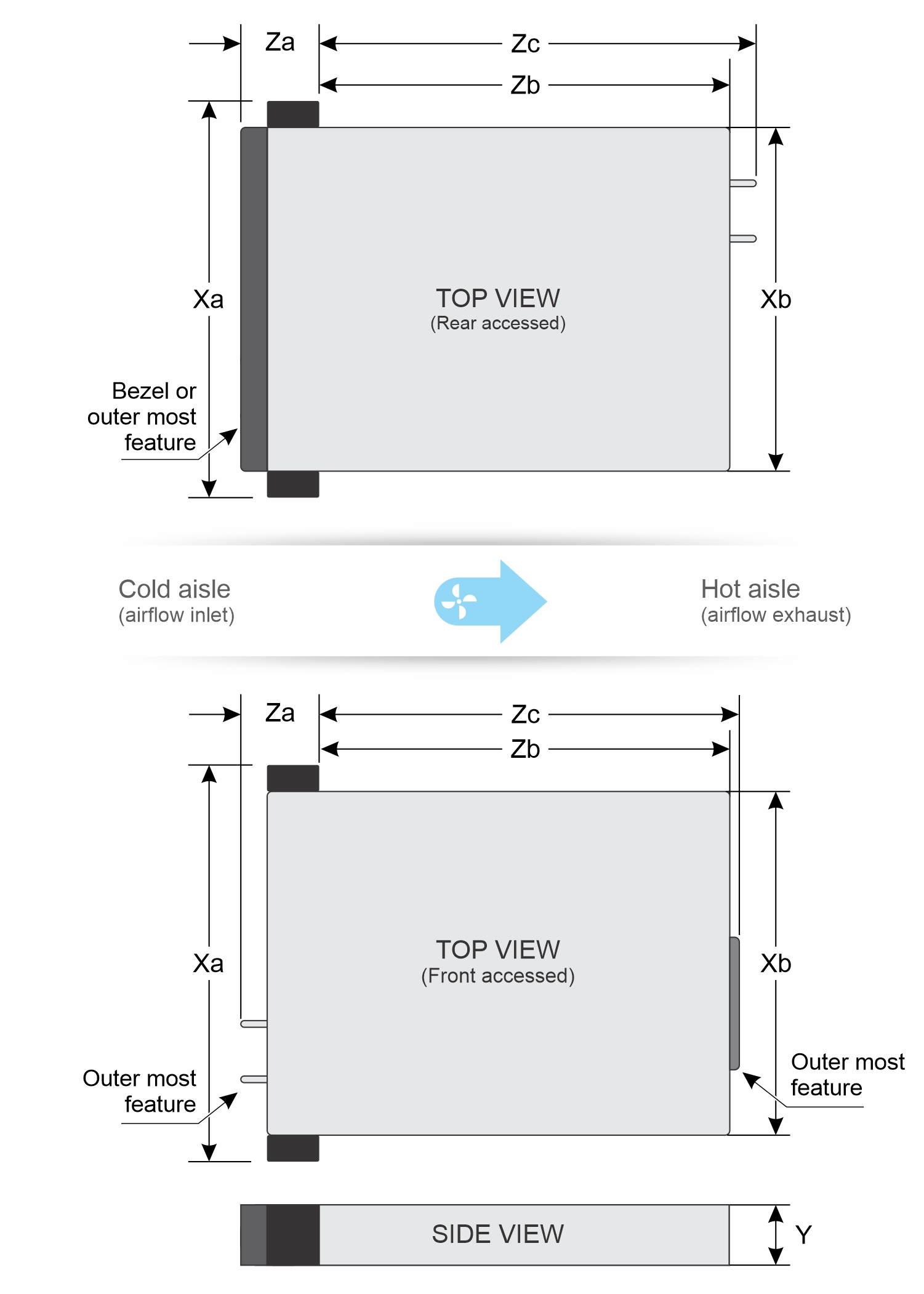
| Drives | Xa | Xb | Y | Za without bezel | Za with bezel | Zb | Zc |
|---|---|---|---|---|---|---|---|
| Rear Accessed configuration | 482.6 mm (19 inches) | 434 mm (17 inches) | 42.8 mm (1.68 inches) | 22.0 mm (0.86 inches) | 47 mm (1.85 inches) Back of rack ear to most outer surface of bezel | 435 mm (17.12 inches) Back of ear to main IO wall | 442 mm (17.40 inches) Back of ear to PSU handle |
| Front Accessed configuration | 482.6 mm (19 inches) | 434.0 mm (17 inches) | 42.8 mm (1.68 inches) | 47.75 mm (1.88 inches) (left ear)
31.35 mm (1.23 inches) (right ear) | 148 mm (5.82 inches) Back of rack ear to most outer surface of bezel | 409 mm (16.10 inches) Back of ear to chassis face | 417 mm (16.41 inches) Back of ear to MIL drive bracket edge |
System weight
| System configuration | Maximum weight (with all drives/SSDs/rails/bezel) |
|---|---|
| Rear Accessed configuration | 11.27 kg (24.8 lb) |
| Front Accessed configuration | 11.37 kg (25.1 lb) |
Processor specifications
| Supported processor | Number of processor supported |
|---|---|
| 4th Generation and 5th Generation Intel Xeon Scalable and Edge-Enhanced processor and Edge-Enhanced CPUs with up to 32 cores | One |
PSU specifications
The PowerEdgeXR5610system supports up to two AC or DC power supply units (PSUs).
| PSU | Class | Heat dissipation (maximum) | Frequency | Voltage | DC | DC | Current | |
|---|---|---|---|---|---|---|---|---|
| High line 240 V DC | Low line | |||||||
| 1800 W Mixed Mode | Titanium | 5406 BTU/hr | 50/60 Hz | 200-240 V AC, autoranging | 1800 W | 1050 W | N/A | 10 A |
| Titanium | 5406 BTU/hr | N/A | 240 V DC | N/A | N/A | 1400 W | 8.2 A | |
| 1400 W Mixed Mode | Platinum | 5406 BTU/hr | 50/60 Hz | 100–240 V AC, autoranging | 1400 W | 1050 W | N/A | 12 A-8 A |
| Platinum | 5406 BTU/hr | N/A | 240 V DC | N/A | N/A | 1400 W | 6.6 A | |
| 1100 W Mixed Mode | Titanium | 4299 BTU/hr | 50/60 Hz | 100–240 V AC, autoranging | 1100 W | 1050 W | N/A | 12 A-6.3 A |
| Titanium | 4299 BTU/hr | N/A | 240 V DC | N/A | N/A | 1100 W | 5.2 A | |
| 1100 W DC | N/A | 4265 BTU/hr | N/A | -48-(-60) V | N/A | N/A | 1100 W | 27 A |
| 800 W Mixed Mode | Platinum | 3000 BTU/hr | 50/60 Hz | 100–240 V AC, autoranging | 800 W | 800 W | 800 W | 9.2 A-4.7 A |
| Platinum | 3000 BTU/hr | N/A | 240 V DC | N/A | N/A | 800 W | 3.8A | |
Power cords
| Form factor | Output | Power cord |
|---|---|---|
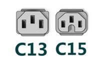
| Redundant 60 mm | 800 W Mixed Mode | C13 |
| 1100 W Mixed Mode | C13 | |
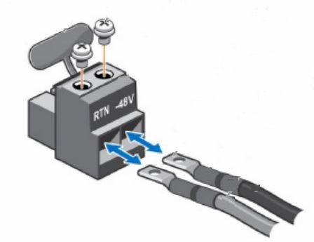
| 1100 W -48—(-60) V DC | DC power cable | |
| 1400 W Mixed Mode | C15 | |
| 1800 W Mixed Mode | DC power cable |
Supported operating systems
The PowerEdge XR5610 system supports the following operating systems:
- Canonical Ubuntu Server LTS
- Microsoft Windows Server with Hyper-V
- Red Hat Enterprise Linux
- SUSE Linux Enterpriser Server
- VMware ESXi
- Dell NativeEdge OS
For more information, go to OS support.
Cooling fans specifications
The PowerEdge XR5610 system supports six standard fans and requires all six fans to be installed.
System battery specifications
The PowerEdge XR5610 system supports CR 2032 3.0-V lithium coin cell system battery.
Expansion card riser specifications
| PCIe slot | Risers | PCIe slot height | PCIe slot length | PCIe slot width |
|---|---|---|---|---|
| Slot 1 | Riser 3 | Full height | Half Length | x16 |
| Slot 2 | Riser 3 | Full height | Half length | x16 |
| Slot 3 | Riser 1 (FLOP) | N/A | N/A | x16 |
Memory specifications
| DIMM type | DIMM rank | DIMM capacity | Single processor | |
|---|---|---|---|---|
| Minimum RAM | Maximum RAM | |||
| RDIMM | Single rank | 16 GB | 16 GB | 128 GB |
| Dual rank | 32 GB | 32 GB | 256 GB | |
| Dual rank | 64 GB | 64 GB | 512 GB | |
| Dual rank | 96 GB | 96 GB | 768 GB | |
| Quad rank | 128 GB | 128 GB | 1 TB | |
| Memory module sockets | Speed |
|---|---|
| 8, 288-pin | 4800 MT/s |
Storage controller specifications
| Supported storage controller cards |
|---|
Software RAID
|
Internal controllers
NOTE:PERC H965e is not compatible with Intel Ethernet 100G 2P E810-—2C Adapter.
|
External controllers
|
Internal boot
|
SAS host bus adapters
|
Drives specifications
USB ports specifications
| Front | Rear | ||
|---|---|---|---|
| USB port type | No. of ports | USB port type | No. of ports |
| USB 2.0-compliant port | One | USB 3.0-compliant port | One |
| iDRAC Direct port (Micro-AB USB 2.0-compliant port) | One | ||
| Front | Rear | ||
|---|---|---|---|
| USB port type | No. of ports | USB port type | No. of ports |
| USB 3.0-compliant port | One | None | |
| iDRAC Direct port (Micro-AB USB 2.0-compliant port) | One | ||
Display port specifications
The PowerEdge XR5610 system supports 1 x Mini-DisplayPort on the rear of the Rear Accessed configuration and on the front of the Front Accessed configuration.
GPU specifications
The PowerEdge XR5610 system supports up to two 75 W/150 W (single-width, low-profile, and half-length) GPUs.
iDRAC9 port specifications
Serial connector specifications
The PowerEdge XR5610 system supports one Micro USB Type B serial connector that is located on the rear of the Rear Accessed configuration and on the front of the Front Accessed configuration.
RJ45 dry contact
To enhance usage in IoT space, the XR5610 comes with dry input sensor. Each input are configurable and manageable in the iDRAC interface. These are interruptible inputs to iDRAC. Dry means no energy is supplied to the contacts.
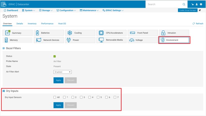
The default state of the dry inputs are off/disabled. User will have 7 (one for each dry input) enable/disable (default) control that must be enabled before logging will occur.
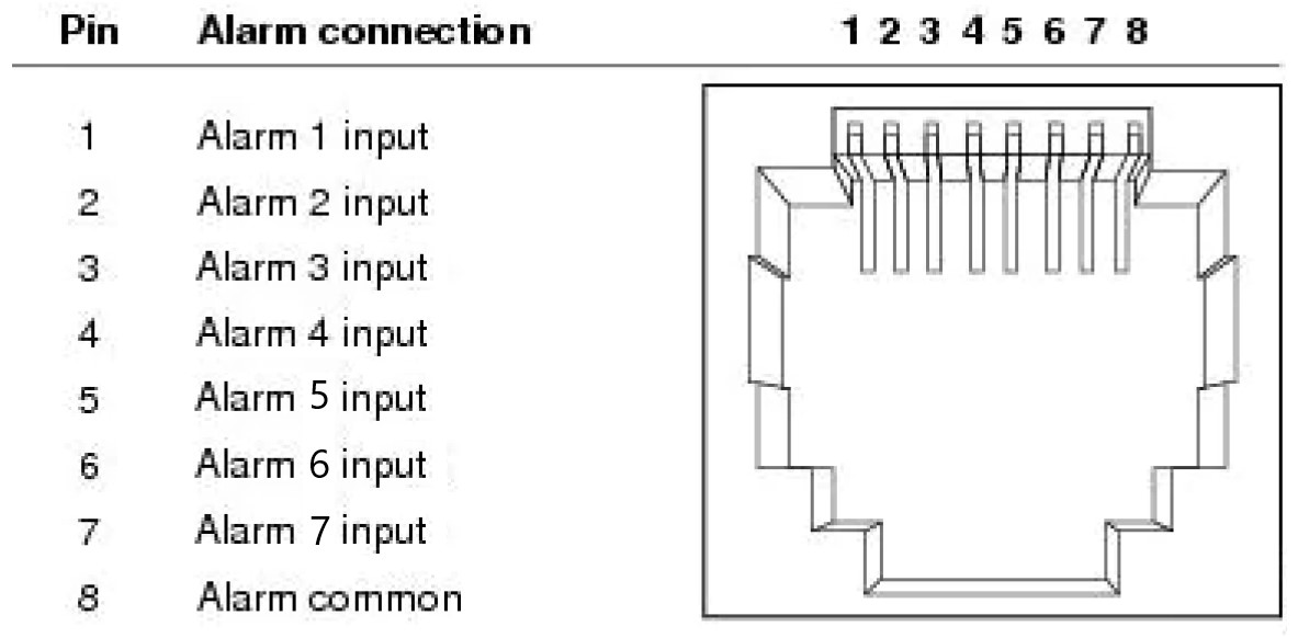
The 7 dry inputs are interruptible inputs to iDRAC.They have the following characteristics:
- Monitored by iDRAC for state transition and LC event will be logged for each state transition.
- NOT modeled as IPMI sensors but LC event only sensors. The current state of the input is not monitored or displayed anywhere.
- Event Log - transitions (Open to close or close to Open) will be logged in LC only.
| Message ID | Message | RRA | DD | Severity |
|---|---|---|---|---|
| DCI1000 | Dry input <input index> is transitioned to Open state. | None. | None | Severity -3 (Info) |
| DCI1001 | Dry input <input index> is transitioned to Close state. | None. | None | Severity -3 (Info) |
NIC port specifications
There is also a dedicated iDRAC management port that supports 1GbE.
| Feature | Specifications |
|---|---|
| LOM | 10 GbE, 25 GbE
NOTE:The lowest connection speed for LOM is 10 GbE.
|
| RJ45 for iDRAC | 1 GbE |
| OCP card (3.0) | 1 GbE, 10 GbE, 25 GbE |
Video specifications
| Resolution | Refresh Rate | Color depth (Bits) |
|---|---|---|
| 1024 x 768 | 60 Hz | 8, 16, 32 |
| 1280 x 800 | 60 Hz | 8, 16, 32 |
| 1280 x 1024 | 60 Hz | 8, 16, 32 |
| 1360 x 768 | 60 Hz | 8, 16, 32 |
| 1440 x 900 | 60 Hz | 8, 16, 32 |
| 1600 x 900 | 60 Hz | 8, 16, 32 |
| 1600 x 1200 | 60 Hz | 8, 16, 32 |
| 1680 x 1050 | 60 Hz | 8, 16, 32 |
| 1920 x 1080 | 60 Hz (RB) | 8, 16, 32 |
| 1920 x 1200 | 60 Hz (RB) | 8, 16, 32 |
Environmental specifications
| Feature | Allowable continuous operations |
|---|---|
| Temperature range for altitudes <= 900 m (<= 2953 ft) | 10–35°C (50–95°F) with no direct sunlight on the equipment |
| Humidity percent range (non-condensing at all times) | 8% RH with -12°C minimum dew point to 80% RH with 21°C (69.8°F) maximum dew point |
| Operational altitude de-rating | Maximum temperature is reduced by 1°C/300 m (33.8°F/984 Ft) above 900 m (2953 Ft) |
| Feature | Allowable continuous operations |
|---|---|
| Temperature range for altitudes <= 900 m (<= 2953 ft) | 5–40°C (41–104°F) with no direct sunlight on the equipment |
| Humidity percent range (non-condensing at all times) | 8% RH with -12°C minimum dew point to 85% RH with 24°C (75.2°F) maximum dew point |
| Operational altitude de-rating | Maximum temperature is reduced by 1°C/175 m (33.8°F/574 Ft) above 900 m (2953 Ft) |
| Feature | Allowable continuous operations |
|---|---|
| Temperature range for altitudes <= 900 m (<= 2953 ft) | 5–45°C (41–113°F) with no direct sunlight on the equipment |
| Humidity percent range (non-condensing at all times) | 8% RH with -12°C minimum dew point to 90% RH with 24°C (75.2°F) maximum dew point |
| Operational altitude de-rating | Maximum temperature is reduced by 1°C/125 m (33.8°F/410 Ft) above 900 m (2953 Ft) |
| Feature | Allowable continuous operations |
|---|---|
| Temperature range for altitudes <= 900 m (<= 2953 ft) | (-5)–55°C (23–131°F) with no direct sunlight on the equipment |
| Humidity percent range (non-condensing at all times) | 8% RH with -12°C minimum dew point to 90% RH with 24°C (75.2°F) maximum dew point |
| Operational altitude de-rating | Maximum temperature is reduced by 1°C/80 m (33.8°F/410 Ft) above 900 m (2953 Ft) |
| Feature | Allowable continuous operations |
|---|---|
| Maximum temperature gradient (applies to both operation and non-operation) | 20°C in an hour* (36°F in an hour) and 5°C in 15 minutes (41°F in 15 minutes), 5°C in an hour* (41°F in an hour) for tape
NOTE:* - Per ASHRAE thermal guidelines for tape hardware, these are not instantaneous rates of temperature change.
|
| Non-operational temperature limits | -40 to 65°C (-104 to 149°F) |
| Non-operational humidity limits | 5% to 95% RH with 27°C (80.6°F) maximum dew point |
| Maximum non-operational altitude | 12,000 meters (39,370 feet) |
| Maximum operational altitude | 3,048 meters (10,000 feet) |
| Maximum vibration | Specifications |
|---|---|
| Operating |
|
| Storage |
|
| Maximum shock pulse | Specifications |
|---|---|
| Operating |
|
| Operating (Navy) | MIL-STD-901E, Grade A, Class 2, Type A, in approved military transit case |
| Storage |
|
Particulate and gaseous contamination specifications
| Particulate contamination | Specifications |
|---|---|
| Air filtration | Data center air filtration as defined by ISO Class 8 per ISO 14644-1 with a 95% upper confidence limit.
NOTE:This condition applies to data center environments only. Air filtration requirements do not apply to IT equipment designed to be used outside a data center, in environments such as an office or factory floor.
NOTE:Air entering the data center must have MERV11 or MERV13 filtration.
|
|
Conductive dust |
Air must be free of conductive dust, zinc whiskers, or other conductive particles.
NOTE:This condition applies to data center and non-data center environments.
|
|
Corrosive dust |
NOTE:This condition applies to data center and non-data center environments.
|
| Walk-Up Edge Data Center or Cabinet (sealed, closed loop environment) | Filtration is not required for cabinets that are anticipated to be opened 6 times or less per year. Class 8 per ISO 1466-1 filtration as defined above is required otherwise
NOTE: In environments commonly above ISA-71 Class G1 or that may have known challenges, special filters may be required.
|
| Gaseous contamination | Specifications |
|---|---|
| Copper Coupon Corrosion rate | <300 Å/month per Class G1 as defined by ANSI/ISA71.04-2013 |
| Silver Coupon Corrosion rate | <200 Å/month as defined by ANSI/ISA71.04-2013 |
Rugged certifications and specifications
| Industry | Configuration | Description |
|---|---|---|
| Telco | GR-1089-CORE | Electromagnetic Compatibility and Electrical Safety – Generic Criteria for Network Telecommunications Equipment |
| GR-63-CORE | NEBS Requirements: Physical Protection | |
| SR-3580 (NEBS Level 3) | NEBS Criteria Levels | |
| GR-3108-CORE (Class 1) | Network Equipment in the Outside Plant (OSP). An exception is made for cold boot at 0C instead of -5C. | |
| Military | MILSTD 810H | Environmental engineering considerations and laboratory test |
| MILSTD 461G/// | Requirements for the control of electromagnetic interference characteristic of subsystems and equipment | |
| MILSTD 901E | High impact shock test – Shipboard | |
| MILSTD 1474E | Department of Defense Design Criteria Standard Noise Limits |
Thermal restriction matrix
| Chassis configuration | ||||||
|---|---|---|---|---|---|---|
| Ambient temperature | ASHARE A2 (Max 35°C) | ASHARE A3 (Max 40°C) | ASHARE A4 (Max 45°C) | Edge1 (Max 50°C) | Edge2 (Max 55°C) | |
| Intel Xeon Silver 4514Y | 150 W | STD heat sink | STD heat sink | STD heat sink | STD heat sink | HPR heat sink |
| Intel Xeon Gold 6433N | 205 W | STD heat sink | STD heat sink | STD heat sink | HPR heat sink | HPR heat sink |
| Intel Xeon Gold 6423N | 195 W | STD heat sink | STD heat sink | STD heat sink | STD heat sink | HPR heat sink |
| Intel Xeon Gold 6403N | 185 W | STD heat sink | STD heat sink | STD heat sink | STD heat sink | HPR heat sink |
| Intel Xeon Silver 4510 | 150 W | STD heat sink | STD heat sink | STD heat sink | STD heat sink | STD heat sink |
| Intel Xeon Gold 5423N | 145 W | STD heat sink | STD heat sink | STD heat sink | STD heat sink | STD heat sink |
| Intel Xeon Silver 4509Y | 125 W | STD heat sink | STD heat sink | STD heat sink | STD heat sink | STD heat sink |
| Intel Xeon Gold 6438N | 205 W | STD heat sink | STD heat sink | STD heat sink | STD heat sink | HPR heat sink |
| Intel Xeon Gold 6421N | 185 W | STD heat sink | STD heat sink | STD heat sink | STD heat sink | STD heat sink |
| Intel Xeon Gold 5411N | 165 W | STD heat sink | STD heat sink | STD heat sink | STD heat sink | STD heat sink |
| Intel Xeon Gold 5412U | 185 W | STD heat sink | STD heat sink | STD heat sink | STD heat sink | HPR heat sink |
| Intel Xeon Gold 5416S | 150 W | STD heat sink | STD heat sink | STD heat sink | STD heat sink | STD heat sink |
| Intel Xeon Gold 3408U | 125 W | STD heat sink | STD heat sink | STD heat sink | STD heat sink | STD heat sink |
| Chassis configuration | |||||||
|---|---|---|---|---|---|---|---|
| Ambient temperature | ASHARE A2 (Max 35°C) | ASHARE A3 (Max 40°C) | ASHARE A4 (Max 45°C) | Edge1 (Max 50°C) | Edge2 (Max 55°C) | ||
| Memory | DDR5 RDIMM 4800 MT/s 128 GB | Supported | Not supported | Not supported | Not supported | Not supported | |
| DDR5 RDIMM 4800 MT/s 64 GB | Supported | Supported | Supported | Supported | Supported | ||
| DDR5 RDIMM 4800 MT/s 32 GB | Supported | Supported | Supported | Supported | Supported | ||
| DDR5 RDIMM 4800 MT/s 16 GB | Supported | Supported | Supported | Supported | Supported | ||
| DDR5 RDIMM 5600 MT/s 128 GB | Supported | Not supported | Not supported | Not supported | Not supported | ||
| DDR5 RDIMM 5600 MT/s 96 GB | Supported | Not supported | Not supported | Not supported | Not supported | ||
| DDR5 RDIMM 5600 MT/s 64 GB | Supported | Supported | Supported | Supported | Supported | ||
| DDR5 RDIMM 5600 MT/s 32 GB | Supported | Supported | Supported | Supported | Supported | ||
| DDR5 RDIMM 5600 MT/s 16 GB | Supported | Supported | Supported | Supported | Supported | ||
| Chassis configuration | |||||
|---|---|---|---|---|---|
| Ambient temperature | ASHARE A2 (Max 35°C) | ASHARE A3 (Max 40°C) | ASHARE A4 (Max 45°C) | Edge1 (Max 50°C) | Edge2 (Max 55°C) |
| Qualcomm X100 | Supported | ||||
| Dell 100GbE QSFP28 | Supported | ||||
| Nokia Cloud RAN SmartNIC 2x QSFP56-DD | Supported | Not supported | |||
| NVIDIA GPU A2 | A2 supports up to 50°C. | Not supported | |||
| NVIDIA GPU L4 | L4 supports up to 50°C. | Not supported | |||
| 2.5-inch NVMe SSD | NVMe supports up to 35°C. | Not supported | Not supported | Not supported | Not supported |
| 2.5-inch SAS SSD | SAS SSD supports up to 45°C. | SAS SSD supports up to 45°C. | SAS SSD supports up to 45°C. | Not supported | Not supported |
| PCIe COMM Card | Non-Dell qualified PCIe COMM cards are not supported. | ||||
| OCP COMM Card | Non-Dell qualified OCP cards are not supported. | ||||
| Active Optical Cables/Transceivers | SFP transceiver above 2.5 W only with 85°C spec is supported. | ||||
| PSU | Dual PSU in redundant mode is required while ambient > 50°C, single PSU is not supported. | ||||
| Chassis configuration | ||||||
|---|---|---|---|---|---|---|
| Ambient temperature | ASHARE A2 (Max 35°C) | ASHARE A3 (Max 40°C) | ASHARE A4 (Max 45°C) | Edge1 (Max 50°C) | Edge2 (Max 55°C) | |
| Intel Xeon Silver 4514Y | 150 W | STD heat sink | STD heat sink | STD heat sink | HPR heat sink | Not supported |
| Intel Xeon Gold 6433N | 205 W | STD heat sink | STD heat sink | STD heat sink | STD heat sink | HPR heat sink |
| Intel Xeon Gold 6423N | 195 W | STD heat sink | STD heat sink | STD heat sink | STD heat sink | STD heat sink |
| Intel Xeon Gold 6403N | 185 W | STD heat sink | STD heat sink | STD heat sink | STD heat sink | STD heat sink |
| Intel Xeon Silver 4510 | 150 W | STD heat sink | STD heat sink | STD heat sink | STD heat sink | STD heat sink |
| Intel Xeon Bronze 5423N | 145 W | STD heat sink | STD heat sink | STD heat sink | STD heat sink | STD heat sink |
| Intel Xeon Silver 4509Y | 125 W | STD heat sink | STD heat sink | STD heat sink | STD heat sink | STD heat sink |
| Intel Xeon Gold 6438N | 205 W | STD heat sink | STD heat sink | STD heat sink | STD heat sink | STD heat sink |
| Intel Xeon Gold 6421N | 185 W | STD heat sink | STD heat sink | STD heat sink | STD heat sink | STD heat sink |
| Intel Xeon Gold 5412U | 185 W | STD heat sink | STD heat sink | STD heat sink | STD heat sink | HPR heat sink |
| Intel Xeon Gold 5411N | 165 W | STD heat sink | STD heat sink | STD heat sink | STD heat sink | STD heat sink |
| Intel Xeon Gold 5416S | 150 W | STD heat sink | STD heat sink | STD heat sink | STD heat sink | STD heat sink |
| Intel Xeon Bronze 3408U | 125 W | STD heat sink | STD heat sink | STD heat sink | STD heat sink | STD heat sink |
| Chassis configuration | |||||||
|---|---|---|---|---|---|---|---|
| Ambient temperature | ASHARE A2 (Max 35°C) | ASHARE A3 (Max 40°C) | ASHARE A4 (Max 45°C) | Edge1 (Max 50°C) | Edge2 (Max 55°C) | ||
| Memory | DDR5 RDIMM 4800 MT/s 128 GB | Supported | Not supported | Not supported | Not supported | Not supported | |
| DDR5 RDIMM 4800 MT/s 64 GB | Supported | Supported | Supported | Supported | Supported | ||
| DDR5 RDIMM 4800 MT/s 32 GB | Supported | Supported | Supported | Supported | Supported | ||
| DDR5 RDIMM 4800 MT/s 16 GB | Supported | Supported | Supported | Supported | Supported | ||
| DDR5 RDIMM 5600 MT/s 128 GB | Supported | Not supported | Not supported | Not supported | Not supported | ||
| DDR5 RDIMM 5600 MT/s 96 GB | Supported | Not supported | Not supported | Not supported | Not supported | ||
| DDR5 RDIMM 5600 MT/s 64 GB | Supported | Supported | Supported | Supported | Supported | ||
| DDR5 RDIMM 5600 MT/s 32 GB | Supported | Supported | Supported | Supported | Supported | ||
| DDR5 RDIMM 5600 MT/s 16 GB | Supported | Supported | Supported | Supported | Supported | ||
| Chassis configuration | ||||||
|---|---|---|---|---|---|---|
| Ambient temperature | ASHARE A2 (Max 35°C) | ASHARE A3 (Max 40°C) | ASHARE A4 (Max 45°C) | Edge1 (Max 50°C) | Edge2 (Max 55°C) | |
| Qualcomm X100 | Supported | Supported | Supported | Supported | Not supported | |
| Dell 100GbE QSFP28 | Supported | Supported | Supported | Supported | Not supported | |
| Nokia Cloud RAN SmartNIC 2x QSFP56-DD | Supported | Supported | Supported | Not supported | Not supported | |
| M.2 NVMe (BOSS-N1) | Micron 7400 | Support up to 35°C. | Not supported | Not supported | Not supported | Not supported |
| Micron 7450 | Support up to 35°C. | Not supported | Not supported | Not supported | Not supported | |
| Hynix PE8010 | Support up to 35°C. | Not supported | Not supported | Not supported | Not supported | |
| Hynix PE9010 | Support up to 35°C. | Not supported | Not supported | Not supported | Not supported | |
| NVIDIA GPU A2 | A2 supports up to 40°C. | Not supported | Not supported | Not supported | ||
| NVIDIA GPU L4 | L4 supports up to 40°C. | Not supported | Not supported | Not supported | ||
| 2.5-inch NVMe SSD | NVMe supports up to 35°C. | Not supported | Not supported | Not supported | Not supported | |
| 2.5-inch SAS SSD | SAS SSD supports up to 45°C. | Not supported | Not supported | |||
| PERC card with battery | PERC card with battery supports up to 45°C. | Not supported | Not supported | |||
| PCIe COMM Card | Non-Dell qualified PCIe COMM cards are not supported. | |||||
| OCP COMM Card | OCP card support up to 35°C. Non-Dell qualified OCP cards are not supported. | Not supported | Not supported | Not supported | Not supported | |
| Active Optical Cables/Transceivers |
|
Not supported | Not supported | |||
| PSU | Dual PSU in redundant mode is required while ambient > 50°C, single PSU is not supported. | |||||
Other Restrictions
- Hot swap fan is not supported on the XR5610.
- Min. cold boot temperature at ≥ 5°C. System operating temperature is -5°C—55°C.
- DIMM Blank is required on empty slots.
- OCP blank is required while empty slot.
- OCP is not supported with high TDP Edge-Enhanced CPU.
- PCIE blank is required on empty slots.
- PSU blank is required on empty slots.
- 2.5-inch drive blank is required on empty slots.
- Notice that the fan speed may increase at ambient <0°C with SAS/SATA SSD. This indicates that the fan is working as design for overall system stability.
- With Nokia Cloud RAN SmartNIC 2x QSFP56-DD on Rear Accessed Configuration chassis, fan speed may be higher under normal operating temperature.