




























Notes, cautions, and warnings
Dell EMC PowerEdge XR2 overview
- Two Intel ® Xeon ® Processor Scalable Family processors
- 16 DIMM slots
- Integrated M.2 module
- Optional M.2 based Boot Optimized Storage Solution module
- Two redundant power supply units (PSU)
System dimensions
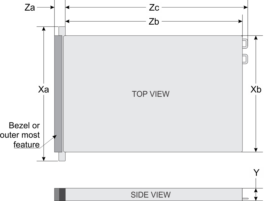
| Xa | Xb | Y | Za (with bezel) | Za (without bezel) | Zb | Zc |
|---|---|---|---|---|---|---|
| 482.6 mm (19 inches) | 434.0 mm (17.08 inches) | 42.8 mm (1.68 inches) | 63.15 mm (2.46 inches) | 33.9 mm (1.32 inches) | 514.35 mm (20.06 inches) | 547.4 mm (21.35 inches) |
Chassis weight
| System | Maximum weight (with all drives/SSDs) |
|---|---|
| 8 x 2.5 inch drive system | 13.00 Kg (28 lb) |
Processor specifications
GPU specifications
Supported Operating Systems
The PowerEdge XR2 supports the following operating systems:
- Red Hat Enterprise Linux
- SUSE Linux Enterprise Server
- Microsoft Windows Server with Hyper-V
- Canonical Ubuntu LTS
- VMware ESXi
- Citrix XenServer
PSU specifications
| PSU | Class | Heat dissipation (maximum) | Frequency | Voltage |
|---|---|---|---|---|
| 550 W AC | Platinum | 2108 BTU/hr | 50/60 Hz | 115–230 V AC |
| 600 W DC | NA | 2016 BTU/hr | NA | -48 V DC |
System battery specifications
Expansion bus specifications
| Expansion card riser | PCIe slots on the riser | Height | Length | Link |
|---|---|---|---|---|
| LOM riser | Slot 1 | Unique to Dell | Unique to Dell | x8 |
| Right riser | Slot 2 | Low Profile | Half Length | x16 |
| Slot 2 | Full Height | Half Length | x16 | |
| Internal riser | Slot-integrated | Platform specific | Platform specific | x8 |
| Left riser | Slot 3 | Low Profile | Half Length | x16 |
Memory specifications
| DIMM type | DIMM rank | DIMM capacity | Single processor | Dual processors | ||
|---|---|---|---|---|---|---|
| Minimum RAM | Maximum RAM | Minimum RAM | Maximum RAM | |||
| RDIMM | Single rank | 8 GB | 8 GB | 80 GB | 16 GB | 128 GB |
| RDIMM | Dual rank | 16 GB | 16 GB | 160 GB | 32 GB | 256 GB |
| RDIMM | Dual rank | 32 GB | 32 GB | 320 GB | 64 GB | 512 GB |
| LRDIMM | Quad rank | 64 GB | 64 GB | 640 GB | 128 GB | 1024 GB |
| LRDIMM | Quad rank | 128 GB | 128 GB | 1024 GB | 256 GB | 2048 GB |
Storage controller specifications
- Internal controllers: PowerEdge Expandable RAID Controller (PERC) H330, H730P, HBA330
- Boot Optimized Storage Subsystem (BOSS): HWRAID 2 x M.2 SSDs 480 GB with 6 Gbps
- x8 connector using PCIe gen 2.0 x2 lanes, available only in the low-profile and half-height form factor
- On board controller: Software RAID (SWRAID) S140
Drives
- Up to 8 x 2.5-inch drives with drive adapter, internal, hot swappable SAS, SATA SSDs
- Up to 4 x 2.5-inch drives with drive adapter, internal, hot swappable NVMe drives
Common Access Card (CAC)
The integrated Common Access Card (CAC) reader or Smart card reader allows for an additional form of authentication for data encryption. The PowerEdge XR2 system supports one CAC on the front panel.
USB ports
- USB 2.0-compliant port on the front panel
- USB 3.0-compliant port on the back panel
The following table provides more information about the USB specifications:
| Front panel | Back panel | Internal USB |
|---|---|---|
|
|
|
eSATA port
The PowerEdge XR2 system supports one eSATA port on the front panel of the system.
NIC ports
Serial connector
VGA ports
Internal Dual MicroSD Module
Video specifications
| Resolution | Refresh rate (Hz) | Color depth (bits) |
|---|---|---|
| 640 x 480 | 60, 70 | 8, 16, 32 |
| 800 x 600 | 60, 75, 85 | 8, 16, 32 |
| 1024 x 768 | 60, 75, 85 | 8, 16, 32 |
| 1152 x 864 | 60, 75, 85 | 8, 16, 32 |
| 1280 x 1024 | 60, 75 | 8, 16, 32 |
| 1440 x 900 | 60 | 8, 16, 32 |
Environmental specifications
| Temperature | Specifications |
|---|---|
| Storage | –40°C–70°C (–40°F–158°F) per Mil-Std 810G Method 501.6, Proc 1 |
| Continuous operation (for altitude less than 950 m or 3117 ft) | 5°C–45°C (41°F–104°F), with no direct sunlight on the equipment |
| Fresh air | For information about fresh air, see Expanded Operating Temperature section. |
| Excursion temperature | 55°C per Mil-Std 810G Method 501.6 Proc II
NOTE Configuration restrictions will apply. For more information, contact DellEMC sales support representative.
|
| Maximum temperature gradient (operating and storage) | 20°C/h (68°F/h) |
| Relative humidity | Specifications |
|---|---|
| Storage | 5% to 95% RH with 33°C (91°F) maximum dew point Atmosphere must be noncondensing at all times. |
| Operating | 5% to 85% relative humidity with 29°C (842°F) maximum dew point |
| Maximum vibration | Specifications |
|---|---|
| Operating | Random vibration per Mil-Std 810G method 514.7, 0.00220783 g2/Hz at 10 Hz to 500 Hz (overall 1.04 rms), all 3 axes, 1 hour per axis |
| Storage | Mil-Std 810G Procedure I, Cat 4, Fig 514.7 C-1 (US highway truck vibration), 1 hour per axes |
| Maximum shock | Specifications |
|---|---|
| Operating | Mil-Std 810G method 516.7, Proc I, 40G, 11 ms, 3 shocks in +/- directions in 3 axes (total 18 shocks) |
| Storage | Mil-Std 810G method 516.7, Proc I, 40G, 11 ms, 3 shocks in +/- directions in 3 axes (total 18 shocks) |
| Maximum altitude | Specifications |
|---|---|
| Operating | Mil-Std 810G method 500.6, Proc. II, air carriage, 15,000 ft for 1 hour after stabilization |
| Storage | Mil-Std 810G method 500.6, Proc. I, 40,000 ft for 1 hour after stabilization |
Standard operating temperature
| Standard operating temperature | Specifications |
|---|---|
| Continuous operation (for altitude less than 950 m or 3117 ft) | +5°C–45°C (41°F–113°F) with no direct sunlight on the equipment
NOTE The 150W CPU support is only up to 35°C.
NOTE GPU continuous operation is supported up to 30°C.
NOTE GPU continuous operation is supported up to 45°C with optional fan booster kit.
|
Expanded operating temperature
| Expanded operating temperature | Specifications |
|---|---|
| Continuous operation | 5°C to 45°C at 5% to 85% RH with 29°C dew point.
NOTE Outside the standard operating temperature (10°C to 35°C), the system can operate continuously in temperatures as low as 5°C and as high as 45°C.
For temperatures between 35°C and 45°C, de-rate maximum allowable temperature by 1°C per 175 m above 950 m (1°F per 319 ft). |
| ≤ 1% of annual operating hours | –5°C to 55°C at 5% to 90% RH with 29°C dew point.
NOTE Outside the standard operating temperature (10°C to 35°C), the system can operate down to –5°C or up to 55°C for a maximum of 1% of its annual operating hours.
NOTE GPU expanded operating temperatures is up to 37°C for selected configurations.
NOTE GPU expanded operating temperatures is up to 50°C for selected configurations with optional fan booster kit.
For temperatures between 45°C and 55°C, de-rate maximum allowable temperature by 1°C per 125 m above 950 m (1°F per 228 ft). |
Expanded operating temperature restrictions
- Do not perform cold start below -15C Per IEC 60945.
- The operating temperature specified is for a maximum altitude of 950 m.
- Redundant power supplies are required.
- Non-Dell qualified peripheral cards and/or peripheral cards greater than 25 W require engineering analysis to see if they can be supported. For more information or support on non-Dell validated components, contact the OEM sales team.
Particulate and gaseous contamination specifications
| Particulate contamination | Specifications |
|---|---|
| Air filtration | Data center air filtration as defined by ISO Class 8 per ISO 14644-1 with a 95% upper confidence limit.
NOTE This condition applies to data center environments only. Air filtration requirements do not apply to IT equipment designed to be used outside a data center, in environments such as an office or factory floor.
NOTE Air entering the data center must have MERV11 or MERV13 filtration.
|
| Conductive dust | Air must be free of conductive dust, zinc whiskers, or other conductive particles.
NOTE This condition applies to data center and non-data center environments.
|
| Corrosive dust |
NOTE This condition applies to data center and non-data center environments.
|
| Gaseous contamination | Specifications |
|---|---|
| Copper coupon corrosion rate | <300 Å/month per Class G1 as defined by ANSI/ISA71.04-1985. |
| Silver coupon corrosion rate | <200 Å/month as defined by AHSRAE TC9.9. |
Documentation resources
This section provides information about the documentation resources for your system.
- From the
Dell EMC support site:
- Click the documentation link that is provided in the Location column in the table.
- Click the required product or product version.
NOTE To locate the product name and model, see the front of your system.
- On the Product Support page, click Manuals & documents.
- Using search engines:
- Type the name and version of the document in the search box.
| Task | Document | Location |
|---|---|---|
| Setting up your system |
For more information about installing and securing the system into a rack, see the Rail Installation Guide included with your rack solution. For information about setting up your system, see the Getting Started Guide document that is shipped with your system. |
www.dell.com/poweredgemanuals |
| Configuring your system | For information about the iDRAC features, configuring and logging in to iDRAC, and managing your system remotely, see the Integrated Dell Remote Access Controller User's Guide.
For information about understanding Remote Access Controller Admin (RACADM) subcommands and supported RACADM interfaces, see the RACADM CLI Guide for iDRAC. For information about Redfish and its protocol, supported schema, and Redfish Eventing are implemented in iDRAC, see the Redfish API Guide. For information about iDRAC property database group and object descriptions, see the Attribute Registry Guide. |
www.dell.com/poweredgemanuals |
|
For information about earlier versions of the iDRAC documents, see the iDRAC documentation. To identify the version of iDRAC available on your system, on the iDRAC web interface, click ? > About. |
www.dell.com/idracmanuals | |
| For information about installing the operating system, see the operating system documentation. | www.dell.com/operatingsystemmanuals | |
| For information about updating drivers and firmware, see the Methods to download firmware and drivers section in this document. | www.dell.com/support/drivers | |
| Managing your system | For information about systems management software offered by Dell, see the Dell OpenManage Systems Management Overview Guide. | www.dell.com/poweredgemanuals |
| For information about setting up, using, and troubleshooting OpenManage, see the Dell OpenManage Server Administrator User’s Guide. | www.dell.com/openmanagemanuals > OpenManage Server Administrator | |
| For information about installing, using, and troubleshooting Dell OpenManage Essentials, see the Dell OpenManage Essentials User’s Guide. | www.dell.com/openmanagemanuals > OpenManage Essentials | |
| For information about installing, using, and troubleshooting Dell OpenManage Enterprise, see the Dell OpenManage Enterprise User’s Guide. | www.dell.com/openmanagemanuals > OpenManage Enterprise | |
| For information about installing and using Dell SupportAssist, see the Dell EMC SupportAssist Enterprise User’s Guide. | https://www.dell.com/serviceabilitytools | |
| For information about partner programs enterprise systems management, see the OpenManage Connections Enterprise Systems Management documents. | www.dell.com/openmanagemanuals | |
| Working with the Dell PowerEdge RAID controllers | For information about understanding the features of the Dell PowerEdge RAID controllers (PERC), Software RAID controllers, or BOSS card and deploying the cards, see the Storage controller documentation. | www.dell.com/storagecontrollermanuals |
| Understanding event and error messages | For information about the event and error messages that are generated by the system firmware and agents that monitor system components, see the Error Code Lookup. | www.dell.com/qrl |
| Troubleshooting your system | For information about identifying and troubleshooting the PowerEdge server issues, see the Server Troubleshooting Guide. | www.dell.com/poweredgemanuals |
Contacting Dell
Dell provides several online and telephone based support and service options. If you do not have an active internet connection, you can find contact information about your purchase invoice, packing slip, bill, or Dell product catalog. Availability varies by country and product, and some services may not be available in your area. To contact Dell for sales, technical assistance, or customer service issues:
Steps
- Go to www.dell.com/support/home
- Select your country from the drop-down menu on the lower right corner of the page.
- For customized support:
- Enter your system Service Tag in the Enter your Service Tag field.
- Click Submit.
The support page that lists the various support categories is displayed.
- For general support:
- Select your product category.
- Select your product segment.
- Select your product.
The support page that lists the various support categories is displayed.
- For contact details of Dell Global Technical
Support:
- Click Global Technical Support
- The Contact Technical Support page is displayed with details to call, chat, or e-mail the Dell Global Technical Support team.
Documentation feedback
You can rate the documentation or write your feedback on any of our Dell EMC documentation pages and click Send Feedback to send your feedback.
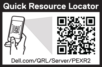
Accessing system information by using QRL
You can use the Quick Resource Locator (QRL) located on the information tag in the front of the PowerEdge R930, to access the information about the PowerEdge R930.
Prerequisites
The QRL includes the following information about your system:
- How-to videos
- Reference materials, including the Installtion and Service Manual, LCD diagnostics, and mechanical overview
- Your system service tag to quickly access your specific hardware configuration and warranty information
- A direct link to Dell to contact technical assistance and sales teams
Steps
- Go to www.dell.com/qrl and navigate to your specific product or
- Use your smartphone or tablet to scan the model-specific Quick Resource (QR) code on your system or in the Quick Resource Locator section.
Quick Resource Locator for PowerEdge XR2
Receiving automated support with SupportAssist
- Automated issue detection — SupportAssist monitors your Dell EMC devices and automatically detects hardware issues, both proactively and predictively.
- Automated case creation — When an issue is detected, SupportAssist automatically opens a support case with Dell EMC Technical Support.
- Automated diagnostic collection — SupportAssist automatically collects system state information from your devices and uploads it securely to Dell EMC. This information is used by Dell EMC Technical Support to troubleshoot the issue.
- Proactive contact — A Dell EMC Technical Support agent contacts you about the support case and helps you resolve the issue.
The available benefits vary depending on the Dell EMC Service entitlement purchased for your device. For more information about SupportAssist, go to www.dell.com/supportassist.
Recycling or End-of-Life service information
Take back and recycling services are offered for this product in certain countries. If you want to dispose of system components, visit www.dell.com/recyclingworldwide and select the relevant country.