




























Sled dimensions
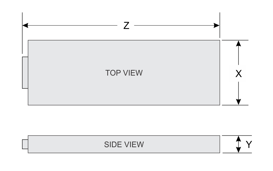
| X | Y | Z |
|---|---|---|
| 438 mm (17.24 inches) | 43.7 mm (1.72 inches) | 819.1 mm (32.24 inches) |
System weight
| System configuration | Maximum weight |
|---|---|
| 8 x E1.S (RC1) | 30.4 kg (67.02 pounds) |
Processor specifications
| Supported processor | Number of processors supported |
|---|---|
| NVIDIA Grace with 72 cores per processor | Two |
Cooling fan specifications
The Server9712asystem supports up to 8 Standard (STD) cooling fans.
| Fan type | Abbreviation | Label color | Label image |
|---|---|---|---|
| Standard fans | STD fan | NA | 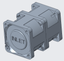 |
| Liquid Cooling | LQ | NA | 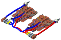 |
Supported operating systems
The 9712a system supports the following operating systems:
- GraceOS
System battery specifications
The Dell server 9712a uses one CR 2032 3.0 V lithium coin cell CR 2032 3.0 V lithium coin-cell battery .
Expansion card riser specifications
| PCIe slot | Expansion card riser | Processor connection | Position | Length | Slot width |
|---|---|---|---|---|---|
| B Bay Left | BlueField-3 (BF3) | Processor 1 | Top layer | Half Length | x16 |
| OSFP | Processor 1 | Bottom layer | Half Length | x16 | |
| B Bay Right (PSB configuration) | BlueField-3 (BF3) | Processor 2 | Top layer | Half Length | x16 |
| OSFP | Processor 2 | Bottom layer | Half Length | x16 | |
| B Bay Right (PSB configuration) | PSB | Processor 2 | Top layer | Half Length | x16 |
| OSFP | Processor 2 | Bottom layer | Half Length | x16 |
Memory specifications
- 480 GB of LP DDR5X memory with error-correction code (ECC) / CPU
- 192 GB HBM3e / GPU
Drives
- Up to 8 x EDSFF E1.S hot-swappable NVMe SSDs
GPU Specifications
- Up to four NVLINK-C2C: 900GB/s of coherent memory of CPU-GPU interconnection.
NIC port Specifications
- 1G Network Interface Controller (NIC) Printed circuit board (PCB) installed in front of the sled.
Video ports specifications
The 9712a system support video using the Mini-Display Port.
Environmental specifications
| Temperature | Specifications |
|---|---|
| Allowable continuous operations | |
| Temperature ranges for altitudes <= 900 m (<= 2953 ft) | 10–35°C (50–95°F) with no direct sunlight on the equipment |
| Humidity percent ranges (non-condensing always) | 8% RH with -12°C minimum dew point to 80% RH with 21°C (69.8°F) maximum dew point |
| Operational altitude derating | Maximum temperature is reduced by 1°C/300 m (33.8°F/984 Ft) above 900 m (2953 Ft) |
| Temperature | Specifications |
|---|---|
| Allowable continuous operations | |
| Maximum temperature gradient (applies to both operation and nonoperation) | 20°C in an hour* (36°F in an hour) and 5°C in 15
minutes (41°F in 15 minutes), 5°C in an hour* (41°F in an hour) for
tape NOTE:* - Per
ASHRAE thermal guidelines for tape hardware, these are not
instantaneous rates of temperature change.
|
| Nonoperational temperature limits | -40 (-5)** to 65°C (-40 (23)** to 149°F) NOTE:**
Liquid filled components, or systems/solutions containing liquid
filled components are limited to approximately 5°C above their
freeze point. The only authorized liquid coolant is Recochem
PG25 with a freeze point between -9°C and -13°C, therefore the
lower nonoperational temperature limit is -5°C. Components and
systems.solutions that can contain liquid but do not at the time
of testing shall be tested to the -40°C lower nonoperational
temperature limit. |
| Nonoperational humidity limits | 5% to 95% RH with 27°C (80.6°F) maximum dew point |
| Maximum nonoperational altitude | 12,000 meters (39,370 ft) |
| Maximum operational altitude | 3,048 meters (10,000 ft) |
| Maximum vibration | Specifications |
|---|---|
| Operating | 0.1 Grms 5 Hz–100 Hz (x, y, and z axes) |
| Storage | 1.1 Grms 2 Hz–500 Hz for 15 min (all six sides tested) |
| Maximum shock pulse | Specifications |
|---|---|
| Operating | 18 consecutively performed half sine shock pulses in the positive and negative x, y, and z axes (three pulses on each side of the system) of six G for up to 11 ms. |
| Storage | Six consecutively performed Trapezoidal Shock pulses in the positive and negative x, y, and z axes (one pulse on each side of the system) of 30 G for up to 11 ms. |
PCIe Configuration Restriction
| Max PCIe Q’ty/Per Sled | PCIe Slot 1 | PCIe Slot 2 |
|---|---|---|
| 1 |
BF3 DPU card (NVIDIA B3240) |
N/A |
| N/A |
BF3 DPU card (NVIDIA B3220) |
|
| 2 |
BF3 DPU card (NVIDIA B3240) |
BF3 DPU card (NVIDIA B3240) |
|
BF3 DPU card (NVIDIA B3220) |
PSB board | |
|
NOTE:NVIDIA Dual QSFP112 Transceiver
(MMA1Z00-NS400) is required for BF3 DPU card.
|
||
| Legend | Configuration | ||||||
|---|---|---|---|---|---|---|---|
| Configuration | Configuration 1 | Configuration 2 | Configuration 3 | Configuration 4 | Configuration 6 | ||
| I/O Board Configuration | CX7 x 2 | CX7 x 2 | CX7 x 2 | CX7 x 2 | CX8 x 2 | ||
| PCIe Configuration | B3240 x 2 | Slot 1: B3220 x 1 Slot 2: PSB x 1 |
B3240 x 2 | Slot 1: B3240 x 1 | Slot 2: B3220 x 1 | ||
| E1.S SSD Configuration |
G4 3.84TB E1.S SSD x 4 (S0, S1, S4, S5) |
G4 3.84TB E1.S SSD x 8 | G4 3.84TB E1.S SSD x 8 | G5 3.84TB E1.S SSD x 2(S0, S1) | G4 7.68TB E1.S SSD x 8 | ||
| BOSS Configuration | 1.92TB M.2 NVMe x 1 | N/A | 1.92TB M.2 NVMe x 1 | 960GB M.2 NVMex 1 | N/A | ||
| CPU TDP | Total TDP | Ambient Temperature | |||||
| CPU TDP | 300 W per Bianca | 2500 W per Bianca1 | 40°C | 40°C | 40°C | 40°C | 40°C |
| GPU TDP | 2x 1200 W per Bianca | ||||||
- CPU can go up to 300W max by borrowing power from GPUs.
- NVIDIA Dual QSFP112 Transceiver (MMA1Z00-NS400) is required for BF3 DPU card.
- NVIDIA Dual OSFP Transceiver (MMS4X00-NS400, MMA4Z00-NS400) is required for CX7 OSFP board.
- NVIDIA Dual OSFP Transceiver (980-9IAT0-00XM00, MMS4X00-NM-FLT, MMS4X00-NS-FLT, MMA4Z00-NS-FLT) is required for CX8 OSFP board.
Particulate and gaseous contamination specifications
The following table defines the limitations that help avoid any equipment damage or failure from particulates and gaseous contamination. If the levels of particulates or gaseous pollution exceed the specified limitations and result in equipment damage or failure, you must rectify the environmental conditions. Remediation of environmental conditions is the responsibility of the customer.
| Particulate contamination | Specifications |
|---|---|
| Air filtration | Data center air filtration as defined by ISO Class 8 per ISO 14644-1 with a 95% upper confidence limit.
NOTE:The ISO Class 8 condition applies to data center environments only. This air filtration requirement does not apply to IT equipment designed to be used outside a data center, in environments such as an office or factory floor.
NOTE:Air entering the data center must have MERV11 or MERV13 filtration
|
| Conductive dust | Air must be free of conductive dust, zinc whiskers, or other conductive particles.
NOTE:This condition applies to data center and non-data center environments.
|
| Corrosive dust |
NOTE:This condition applies to data center and non-data center environments.
|
| Gaseous contamination | Specifications |
|---|---|
| Copper coupon corrosion rate | <300A/month per class G1 as defines by ANSI/ISA71.04-2013 |
| Silver coupon corrosion rate | <200A/month as defined by ANSI/ISA71.04-2013 |