




























Chassis dimensions
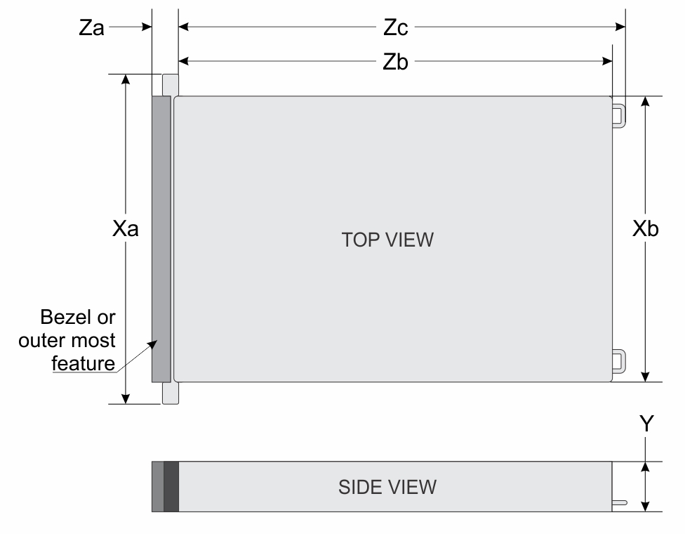
| Drives | Xa | Xb | Y | Za | Zb | Zc |
|---|---|---|---|---|---|---|
16 x E3.S NVMe drives system U.2 NVMe drives system* | 482.3 mm (18.98 inches) | 448 mm (17.63 inches) | 439.5 mm (17.30 inches) | 43.7 mm (1.72 inches)With bezel 22 mm (0.87 inches)Without bezel | 966 mm (38.03 inches) Ear to rear GPU fan | 1001 mm (39.40 inches) Ear to Fan handle |
System Weight
| System Configuration | Maximum Weight (with all drives/SSDs) |
|---|---|
| System fully populated with MI355X GPUs | 172.3 kg (379.86 lb) |
| System fully populated with B300 GPUs | 163.65 kg (360.79 lb) |
| Chassis Weight | Description |
|---|---|
| 40–70 lb | Recommend two people to lift |
| 70–120 lb | Recommend three people to lift |
| ≥ 121 lb | Recommend to use a server-lift |
Processor specifications
| Supported processor | Number of processors supported |
|---|---|
| 5th Generation AMD EPYC 9005 Series processor | Two |
PSU Specifications
The PowerEdgeXE9785system supports 12 AC power supply units (PSUs).
| PSU | Power Ratings | Class | Heat dissipation | Frequence (Hz) | Input Voltage | Current (A) |
|---|---|---|---|---|---|---|
| 3200 W
Mixed Mode (Multi-rated) | 3200 W | Titanium | 11,850 BTU/hr | 50/60 | 216.1-240 VAC | 16 |
| N/A | 11,850 | N/A | 240 VDC | 14.5 | ||
| 2900 W | N/A | 10,750 | 50/60 | 200-216 VAC | 16 |
The power consumption of the system depends on its total power requirements, which vary based on the configuration (as in, number of GPUs, PSUs, and other components). Each PSU model (3200 W) can deliver power up to its rated capacity, but the actual power that is delivered will depend on the system’s needs.
To determine how much power each PSU delivers, the total system power requirement is divided by the number of PSUs in the system. For detailed power usage information, refer to the iDRAC web GUI for real-time power metrics and system monitoring.
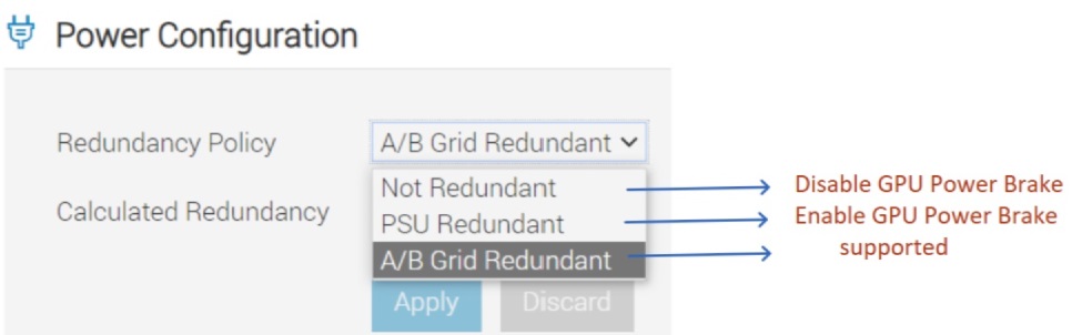
The PowerEdgeXE9785 system also supports 6+6 FTR redundancy. When the Redundancy policy is set to PSU redundant, and when the numbers of failed PSUs exceeds the number required for redundancy, a fault-tolerant redundant mode is activated. This mode triggers the GPU power brake, throttling GPU clocks to one-fourth their normal rate, and resulting in a GPU performance drop to around one-fifth. It is important to note that this feature is applicable only when the system is set to PSU redundant mode. In configurations where PSU redundancy is not enabled, the fault-tolerant redundant mode does not automatically trigger GPU Power Brake.
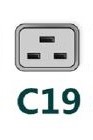
| Form factor | Output | Power cable |
|---|---|---|
| Redundant 73.5 mm | 3200 W mixed mode | C19 |
Cooling fan specifications
The PowerEdgeXE9785 system supports up to:
- 15 standard grade hot-swappable GPU fans installed in the GPU fan sled.
- 5 Standard grade cold-swappable CPU fans installed in the HPM sled.
| Fan type | Abbreviation | Also known as | Label color | Label image |
|---|---|---|---|---|
| Standard (STD) CPU fan | STD | Mid Compute Fan | N/A | 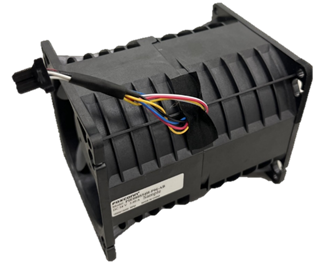 |
| Standard (STD) GPU fan | STD | Rear GPU Fans | N/A | NOTE:New cooling fans
comes with the Rear GPU fans label. 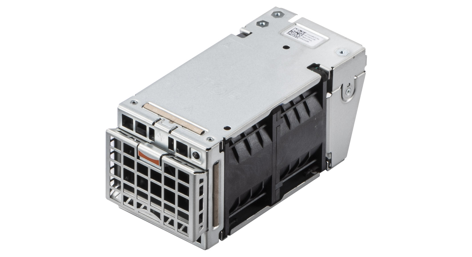 |
System battery specifications
The PowerEdge XE9785 system uses one CR 2032 3.0-V lithium coin cell battery.
Supported operating systems
The PowerEdge XE9785 system supports the following operating system:
- Canonical Ubuntu Server LTS
- Red Hat Enterprise Linux*
Expansion Card Specifications
The PowerEdge XE9785 system supports the following:
- Up to 12 x 75 W Gen5 x16 FHHL cards (PCIe) installed on the PCIe Switch Base Board (PSBB) for MI355X GPU configuration.
- Up to 4 x 150 W Gen5 x16 FHHL cards (PCIe) installed on the PCIe Switch Retimer Base Board (PSRBB) for B300 GPU configuration.
| Platform | Location | Processor Connection | PCIe Slot Height | PCIe Slot Length | Bandwidth | |||
|---|---|---|---|---|---|---|---|---|
| CPU0 - PCIe SW1 | CPU0 - PCIe SW2 | CPU1 - PCIe SW3 | CPU1 - PCIe SW4 | |||||
| PSBB-MI355X | OCP Slot 1 | Processor 2 | N/A | Half Length | N/A | N/A | N/A | x16 |
| PCIe Slot 2 | Processor 2 | Full Height | Half Length | N/A | N/A | N/A | x16 | |
| PCIe Slot 3 | Processor 2 | Full Height | Half Length | N/A | N/A | N/A | x16 | |
| PCIe Slot 4 | Processor 2 | Full Height | Half Length | N/A | N/A | N/A | x16 | |
| PCIe Slot 5 | Processor 2 | Full Height | Half Length | N/A | N/A | x16 | N/A | |
| PCIe Slot 6 | Processor 2 | Full Height | Half Length | N/A | N/A | x16 | N/A | |
| PCIe Slot 7 | Processor 2 | Full Height | Half Length | N/A | N/A | x16 | N/A | |
| PCIe Slot 8 | Processor 1 | Full Height | Half Length | N/A | x16 | N/A | N/A | |
| PCIe Slot 9 | Processor 1 | Full Height | Half Length | N/A | x16 | N/A | N/A | |
| PCIe Slot 10 | Processor 1 | Full Height | Half Length | N/A | x16 | N/A | N/A | |
| PCIe Slot 11 | Processor 1 | Full Height | Half Length | x16 | N/A | N/A | N/A | |
| PCIe Slot 12 | Processor 1 | Full Height | Half Length | x16 | N/A | N/A | N/A | |
| PCIe Slot 13 | Processor 1 | Full Height | Half Length | x16 | N/A | N/A | N/A | |
| GPU Slot 21 | Processor 2 | N/A | Full Length | N/A | N/A | N/A | x16 | |
| GPU Slot 22 | Processor 2 | N/A | Half Length | N/A | N/A | x16 | N/A | |
| GPU Slot 23 | Processor 1 | N/A | Half Length | N/A | x16 | N/A | N/A | |
| GPU Slot 24 | Processor 1 | N/A | Full Length | x16 | N/A | N/A | N/A | |
| GPU Slot 25 | Processor 2 | N/A | Full Length | N/A | N/A | N/A | x16 | |
| GPU Slot 26 | Processor 2 | N/A | Full Length | N/A | N/A | x16 | N/A | |
| GPU Slot 27 | Processor 1 | N/A | Full Length | N/A | x16 | N/A | N/A | |
| GPU Slot 28 | Processor 1 | N/A | Half Length | x16 | N/A | N/A | N/A | |
| Platform | Location | Processor Connection | PCIe Slot Height | PCIe Slot Length | Bandwidth | |
|---|---|---|---|---|---|---|
| CPU0 - PCIe SW1 | CPU1 - PCIe SW2 | |||||
| PSRBB-B300 | OCP Slot 1 | Processor 2 | Full Height | Half Length | N/A | x16 |
| Slot 3 | Processor 2 | Full Height | Half Length | N/A | x16 | |
| Slot 6 | Processor 2 | Full Height | Half Length | N/A | x16 | |
| Slot 9 | Processor 1 | Full Height | Half Length | x16 | N/A | |
| Slot 12 | Processor 1 | Full Height | Half Length | x16 | N/A | |
Memory Specification
The XE9785 supports up to 24 DIMMs (12 per socket), with up to 6 TB of memory and speeds of up to 6400 MT/s.
The XE9785 support registered (RDIMMs) which use a buffer to reduce memory loading and provide greater density, allowing for the maximum platform memory capacity. Unbuffered DIMMs (UDIMMs) are not supported.
| Feature | PowerEdge XE9785 (DDR5) |
|---|---|
| DIMM type | RDIMM |
| Transfer speed | Up to 6400 MT/s NOTE: Maximum DIMM
transfer speed support dependent on CPU SKU and DIMM population.
|
| Voltage | 1.1 V |
| Rated DIMM Speed (MT/s) | DIMM Type | DIMM Capacity (GB) | Ranks per DIMM | Data Width | DIMM Volts (V) |
|---|---|---|---|---|---|
| 6400 | RDIMM | 96 | 2 | x4 | 1.1 |
| 6400 | RDIMM | 128 | 2 | x4 | 1.1 |
| 6400 | RDIMM | 256 | 8 | x4 | 1.1 |
Storage controller specifications
| Supported storage controller cards | |
|---|---|
Internal Boot
|
Drives
- 16 x EDSFF E3.S NVMe (SSD) hot-swappable drives
- 10 x U.2 NVMe (SSD) hot-swappable drives*
GPU Specifications
- 8 AMD Instinct™ MI355X 288 GB 1400 W OAM with AMD Infinity Fabric connectivity GPUs or
- 8 NVIDIA HGX B300 NVL8 270 GB 1100 W SXM6 GPUs, fully interconnected with NVIDIA NVLink technology GPUs
Power Capping Configuration with MI355X GPU
The PowerEdge XE9785 system with MI355X GPU, with a standard thermal design power (TDP) of 1.4 kW per GPU, can be permanently power capped at 1 kW per GPU by the Dell factory upon request. Power capping is implemented through Dell firmware on systems that are ordered as power-limited systems.
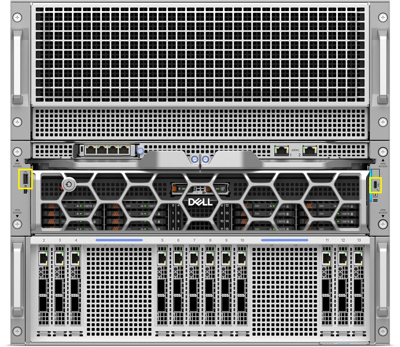
USB Ports Specifications
| Front | Internal | ||
|---|---|---|---|
| USB port type | No. of ports | USB port type | No. of ports |
| USB Type A | One | USB 3.1-compliant port | One |
| USB type C dual-mode host/BMC Direct port | One | ||
NIC port specifications
| Feature | Specifications |
|---|---|
| Ethernet ports on the Front I/O board | 2 x 1 Gb |
| OCP NIC 3.0 card | 200 GbE x 2, 100 GbE x 2, 25 GbE x 4, 25 GbE x 2, 10 GbE x 4, 10G x 2 |
| DPU card | 400 GbE x 2*, 200 GbE x 2 |
| PCIe Add-in Card (AIC) NIC | 400 GbE x 1, 200 GbE x 2, 100 GbE x 2 |
Mini-DisplayPort specifications
The PowerEdge XE9785 system supports One Mini-DisplayPort on left control panel of the system.
iDRAC10 port specifications
Video specifications
| Resolution | Refresh rate (Hz) | Color depth (bits) |
|---|---|---|
| 640 x 480 | 60 | 8, 16, 32 |
| 800 x 600 | 60 | 8, 16, 32 |
| 1024 x 768 | 60 | 8, 16, 32 |
| 1152 x 864 | 60 | 8, 16, 32 |
| 1280 x 800 | 60 | 8, 16, 32 |
| 1280 x 1024 | 60 | 8, 16, 32 |
| 1360 x 768 | 60 | 8, 16, 32 |
| 1400 x 1050 | 60 | 8, 16, 32 |
| 1440 x 900 | 60 | 8, 16, 32 |
| 1600 x 1200 | 60 | 8, 16, 32 |
| 1680 x 1050 | 60 | 8, 16, 32 |
| 1920 x 1080 | 60 | 8, 16, 32 |
| 1920 x 1200 | 60 | 8, 16, 32 |
Environmental specifications
| Parameters | Allowable continuous operations |
|---|---|
| Temperature range for altitudes <= 900 m (<= 2953 ft) | 10–35°C (50–95°F) with no direct sunlight on the equipment |
| Humidity percent range (non-condensing at all times) | 8% RH with -12°C minimum dew point to 80% RH with 21°C (69.8°F) maximum dew point |
| Operational altitude de-rating | Maximum temperature is reduced by 1°C/300 m (33.8°F/984 Ft) above 900 m (2953 Ft) |
| Parameters | Allowable continuous operations |
|---|---|
| Maximum temperature gradient (applies to both operation and non-operation) | 20°C in an hour* (36°F in an hour) and 5°C in 15 minutes (41°F in 15 minutes), 5°C in an hour* (41°F in an hour) for tape
NOTE:* - Per ASHRAE thermal guidelines for tape hardware, these are not instantaneous rates of temperature change.
|
| Non-operational temperature limits | -40°C to 65°C (-40°F to 149°F) |
| Non-operational humidity limits | 5% to 95% RH with 27°C (80.6°F) maximum dew point |
| Maximum non-operational altitude | 12,000 meters (39,370 ft) |
| Maximum operational altitude | 3,048 meters (10,000 ft) |
| Maximum vibration | Specifications |
|---|---|
| Operating | 0.21 Grms at 5 Hz to 500 Hz (all operation orientations) |
| Storage | 1.38 Grms at 7 Hz to 250 Hz for 15 minutes |
| Maximum shock pulse | Specifications |
|---|---|
| Operating | Six consecutively performed shock pulses in the positive and negative x, y, and z axis of 6 G for up to 11 ms. |
| Storage | Executed shock pulses in z axis (one pulse) of 71G for up to 2ms |
Particulate and gaseous contamination specifications
The following table defines the limitations that help avoid any equipment damage or failure from particulates and gaseous contamination. If the levels of particulates or gaseous pollution exceed the specified limitations and result in equipment damage or failure, you must rectify the environmental conditions. Remediation of environmental conditions is the responsibility of the customer.
| Particulate contamination | Specifications |
|---|---|
| Air filtration: Conventional Data Center only | Data center air filtration as defined by ISO Class 8 per ISO 14644-1 with a 95% upper confidence limit
NOTE: Filtering room air with a MERV8 filter, as specified in ANSI/ASHRAE Standard 127, is a recommended method for achieving the necessary environmental conditions.
NOTE:Air entering the data center must have MERV11 or MERV13 filtration.
NOTE:This condition applies to data center environments only. Air filtration requirements do not apply to IT equipment designed to be used outside a data center, in environments such as an office or factory floor.
|
| Walk-Up Edge Data Center or Cabinet (sealed, closed loop environment) | Filtration is not required for cabinets that are anticipated to be opened six times or less per year. Class 8 per ISO 1466-1 filtration as defined above is required otherwise.
NOTE: In environments commonly above ISA-71 Class G1 or that may have known challenges, special filters may be required.
|
| Conductive dust: data center and non-data center environments | Air must be free of conductive dust, zinc whiskers, or other conductive particles.
NOTE: Conductive dust, which can interfere with equipment operation, can originate from various sources, including manufacturing processes and zinc whiskers that may develop on the plating of raised floor tiles.
NOTE:This condition applies to data center and non-data center environments.
|
| Corrosive dust: data center and non-data center environments |
NOTE:This condition applies to data center and non-data center environments.
|
| Gaseous contamination | Specifications | Notes |
|---|---|---|
| Copper coupon corrosion rate | ISA-71 Class G1: <300 Å/month | Per ANSI/ISA71.04 |
| Silver coupon corrosion rate | ISA-71 Class G1: <200 Å/month | Per ANSI/ISA71.04 |
Thermal restriction matrix
| Configuration | STD HSK; CPU STD Fan | |||||||
|---|---|---|---|---|---|---|---|---|
| 16 x E3.S | 10 x U.2* | |||||||
| Component | Processor | cTDP (W) | Max cTDP (W) | Cores | 12 x PCIe | 4 x PCIe | 12 x PCIe | 4 x PCIe |
| CPU | 9965 | 500 | 500 | 192 |
STD HSK / STD Fan Max 35°C |
STD HSK / STD Fan Max 35°C |
STD HSK / STD Fan Max 35°C |
STD HSK / STD Fan Max 35°C |
| 9755 | 500 | 500 | 128 |
STD HSK / STD Fan Max 35°C |
STD HSK / STD Fan Max 35°C |
STD HSK / STD Fan Max 35°C |
STD HSK / STD Fan Max 35°C |
|
| 9655 | 400 | 400 | 96 |
STD HSK / STD Fan Max 35°C |
STD HSK / STD Fan Max 35°C |
STD HSK / STD Fan Max 35°C |
STD HSK / STD Fan Max 35°C |
|
| 9575F | 400 | 400 | 64 |
STD HSK / STD Fan Max 35°C |
STD HSK / STD Fan Max 35°C |
STD HSK / STD Fan Max 35°C |
STD HSK / STD Fan Max 35°C |
|
| 9845 | 390 | 400 | 160 |
STD HSK / STD Fan Max 35°C |
STD HSK / STD Fan Max 35°C |
STD HSK / STD Fan Max 35°C |
STD HSK / STD Fan Max 35°C |
|
| 9825 | 390 | 400 | 144 |
STD HSK / STD Fan Max 35°C |
STD HSK / STD Fan Max 35°C |
STD HSK / STD Fan Max 35°C |
STD HSK / STD Fan Max 35°C |
|
| 9475F | 360 | 400 | 48 |
STD HSK / STD Fan Max 35°C |
STD HSK / STD Fan Max 35°C |
STD HSK / STD Fan Max 35°C |
STD HSK / STD Fan Max 35°C |
|
| 9455 | 300 | 300 | 48 |
STD HSK / STD Fan Max 35°C |
STD HSK / STD Fan Max 35°C |
STD HSK / STD Fan Max 35°C |
STD HSK / STD Fan Max 35°C |
|
| Memory | 96GB RDIMM |
STD Fan Max 35°C |
STD Fan Max 35°C |
STD Fan Max 35°C |
STD Fan Max 35°C |
|||
| 128GB RDIMM |
STD Fan Max 35°C |
STD Fan Max 35°C |
STD Fan Max 35°C |
STD Fan Max 35°C |
||||
| 256GB RDIMM |
STD Fan Max 35°C |
STD Fan Max 35°C |
STD Fan Max 35°C |
STD Fan Max 35°C |
||||
| DPU* | B3220* |
STD Fan Max 35°C |
STD Fan Max 35°C |
STD Fan Max 35°C |
STD Fan Max 35°C |
|||
| B3140H* |
STD Fan Max 35°C |
STD Fan Max 35°C |
STD Fan Max 35°C |
STD Fan Max 35°C |
||||
| B3240* |
STD Fan Max 35°C |
STD Fan Max 35°C |
STD Fan Max 35°C |
STD Fan Max 35°C |
||||
| GPU | AMD MI355X |
STD Fan Max 35°C |
STD Fan Max 35°C |
STD Fan Max 35°C |
STD Fan Max 35°C |
|||
| NVIDIA B300 |
STD Fan Max 35°C |
STD Fan Max 35°C |
STD Fan Max 35°C |
STD Fan Max 35°C |
||||
Other Thermal Restrictions
Configurations that support ASHRAE A3 and A4 are not available.
A PCIe blank (DPN: GYP32) is required if no PCIe card is installed in any slot.
A low-profile block is required when installing a low-profile card.
DIMM blanks are required if fewer than 16 DIMMs are installed.
M.2, OCP, and HDD blanks are required if the corresponding components are not installed.
GPU fans are hot-swappable and must be reinstalled within 30 seconds.
Ambient Temp support of max 35°C.