




























Dimensions of the PowerEdge XE7420 sled
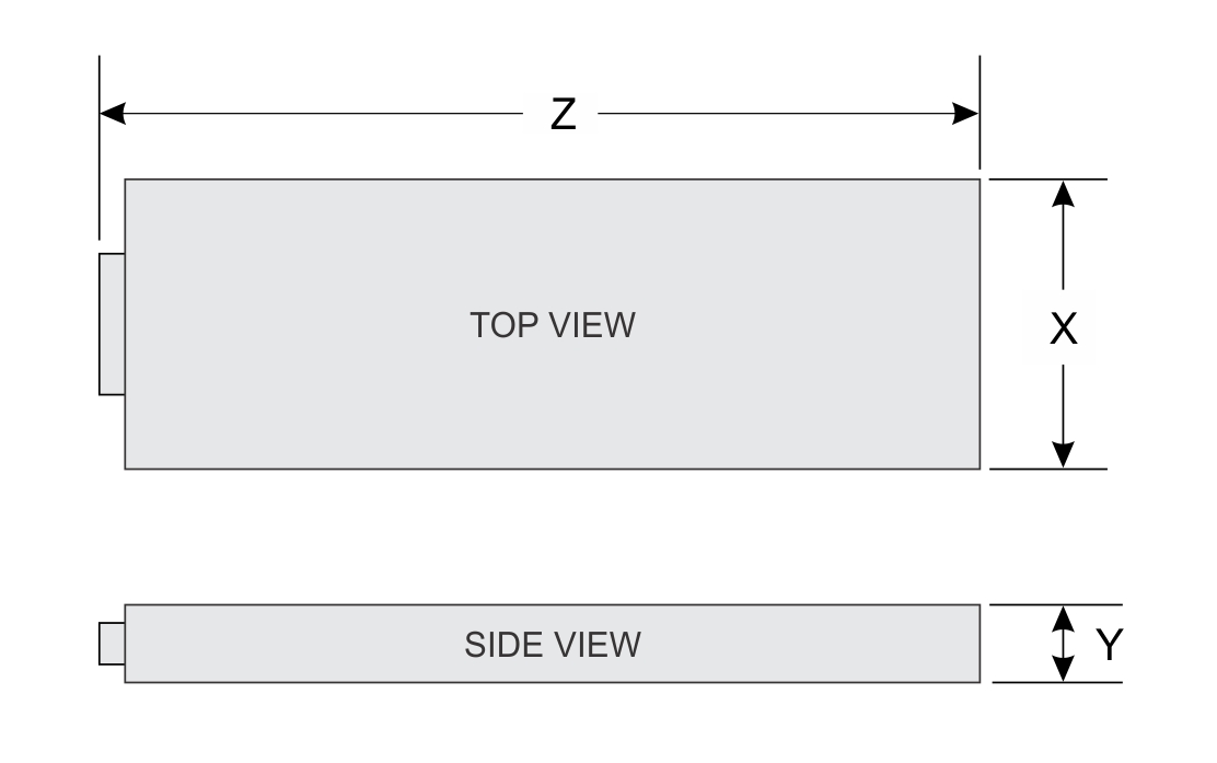
| X | Y | Z |
|---|---|---|
| 187 mm (7.36 inches) | 56.65 mm (2.23 inches) | 691 mm (27.20 inches) |
Chassis weight
| System | Maximum weight (with all sleds and drives) |
|---|---|
| Chassis weight without sled | 132.26 Kg (291.58 lb) |
| Chassis weight with half-width sled (XE7420) | 137.12 Kg (302.29 lb) |
| Chassis weight with full- width full-height sled (XE7440). | 140.93 Kg (310.69 lb) |
| Chassis weight with full- width low-profile sled (XE7440) | 142.81 Kg (341.84 lb) |
PSU specifications
The PowerEdgeXE7100 enclosure supports two AC power supply units (PSUs).
| PSU wattage | Class | Heat dissipation (maximum) | Frequency | Voltage | Maximum input current |
|---|---|---|---|---|---|
| 2400 W AC | Platinum | 9000 BTU/hr | 50/60 Hz | 200-240 V AC, autoranging | 16 A |
PSU redundancy
The PowerEdge XE7100 supports 1+1 redundancy mode.
- In case of a single PSU failure on a fully loaded configuration in 1+1 redundancy mode, system performance may degrade due to power capping.
- Replace the faulty PSU for optimal performance and to resume the 1+1 redundancy mode.
Cooling specifications
The PowerEdge XE7100 chassis with two PowerEdge XE7420 nodes/sleds or one PowerEdge XE7440 node/sled has 18 fans. These are divided into three fan zones (Chassis, Node_A, and Node_B), and each zone has six fans.
The chassis fans are single rotor fans, and sled fans are dual rotor fans.
For Half-Width (HW) sled, sled 1 is Node 1 and sled 2 is Node 2.
| PowerEdge systems | Fan numbering |
|---|---|
| XE7100 - Chassis | 1–6 |
| XE7440 (Single sled) | 7–12 , 13-18 |
| XE7420 (Dual sleds) | Node_A: 7–12 , Node_B: 13-18 |
- For XE7420, the sled 1/ node 1 reports six chassis fan sensors (1-6) and sled 1 fan sensors (7-12).
- For XE7420, the sled 2/ node 2 reports six chassis fan sensors (1-6) and sled 2 fan sensors (13-18).
Cooling fan-mapping
| Fan name and configuration | iDRAC sensor number |
|---|---|
| (Chassis) FAN 1 | 38 |
| FAN 2 | 39 |
| FAN 3 | 3A |
| FAN 4 | 3B |
| FAN 5 | 3C |
| FAN 6 | 3D |
| (Node_A) FAN 7 | 3E |
| FAN 8 | 3F |
| FAN 9 | 40 |
| FAN 10 | 41 |
| FAN 11 | 42 |
| FAN 12 | 43 |
| (Node_B) FAN 13 | 44 |
| FAN 14 | 45 |
| FAN 15 | 46 |
| FAN 16 | 47 |
| FAN 17 | E2 |
| FAN 18 | E3 |
Thermal recommendations
- After one fan rotor failure, you must estimate the fan service time while the system is under steady state.
- It is recommended to limit the minimum service time under 500 seconds.
Power distribution board
Power distribution board (PDB) is also the chassis manager board.
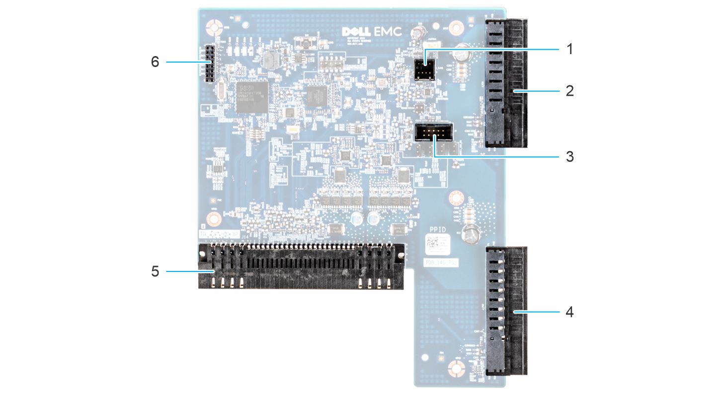
- Intrusion cable connector
- Power supply unit connector 1
- Serial console connector
- Power supply unit connector 2
- Power connector to the HDD backplane/midplane board
- JTAG connector
Drives and storage specifications
The PowerEdge XE7100 enclosure supports SAS and SATA hard drives and Solid State Drives (SSDs).
| Maximum number of drives in the enclosure | Maximum number of drives assigned per sled |
|---|---|
| 100 x 3.5-inch drive systems | 50 SAS or SATA hard drives and SSDs per sled |
| 4 x 2.5-inch drive systems | Four SAS or SATA hard drives and SSDs per sled |
| 4 x 2.5-inch drive systems with NVMe | The NVMe backplane supports either of these configurations:
|
| M.2 SATA drive (optional) | The supported capacity of the M.2 SATA card is up to 240 GB
NOTE:The M.2 SATA card can be installed on
the x8 (slot 1) mezzanine riser or
the x16 riser slot (slot 5).
|
| Micro-SD card (optional) for boot (up to 64 GB) | One on each PCIe riser of each sled |
Installation recommendation for 2.5-inch SSD (7mm) in expander module
- Install HDDs on slots 0, 1, 2, 3
- HDD slots 0 and 1 supports only SATA SSD
- HDD slots 2 and 3 support NVMe and SATA SSDs
Expander module
Dell PowerEdge XE7100 supports up to two expander modules.
Each expander module supports:
- One Microsemi PM8056 SAS expander chip
- Two 2.5 inch slim 7 mm SATA SSDs + two 2.5 inch slim 7 mm NVMe SSDs
- Supports PERC H745P and HBA355i
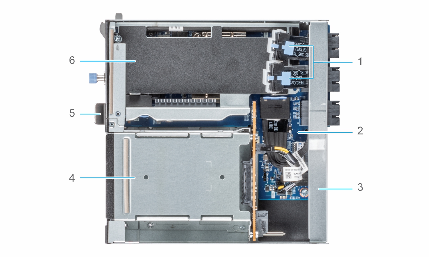
- SAS cables
- Expander board
- Cross bar bracket
- SSD cage
- Pull out lever
- PERC riser
Environmental specifications
The sections below contains information about the environmental specifications of the system.
Standard operating temperature specifications
| Standard operating temperature | Specifications |
|---|---|
| Temperature ranges (for altitude less than 900 m or 2953 ft) | 10°C–35°C (50°F–95°F) with no direct sunlight on the equipment. |
Expanded operating temperature specifications
Operating temperature derating specifications
| Operating temperature derating | Specifications |
|---|---|
| ≤ 35°C (95°F) | Maximum temperature is reduced by 1°C/300 m (1.8°F/984 ft) above 900 meters (2953 ft). |
| 35°C–40°C (95°F–104°F) | Maximum temperature is reduced by 1°C/175 m (1.8°F/574 ft) above 900 meters (2953 ft). |
| 40°C–45°C (104°F–113°F) | Maximum temperature is reduced by 1°C/125 m (1.8°F/410 ft) above 900 meters (2953 ft). |
Relative humidity specifications
| Relative humidity | Specifications |
|---|---|
| Storage | 5% to 95% RH with 27°C (80.6°F) maximum dew point. Atmosphere must be noncondensing always. |
| Operating |
|
Temperature specifications
| Temperature | Specifications |
|---|---|
| Storage | –40°C–65°C (–40°F to 149°F) |
| Continuous operation (for altitude less than 950 m or 3117 ft) | 10°C–35°C (50°F to 95°F) with no direct sunlight on the equipment. |
| Expanded operating temperature | For information about expanded operating temperature, see Expanded Operating Temperature section. |
| Maximum temperature gradient (operating and storage) | 20°C/h (68°F/h) |
Particulate and gaseous contamination specifications
| Particulate contamination | Specifications |
|---|---|
| Air filtration | Data center air filtration as defined by ISO Class 8 per ISO 14644-1 with a 95% upper confidence limit. |
|
NOTE:This condition applies only to data center environments. Air filtration requirements do not apply to IT equipment designed to be used outside a data center, in environments such as an office or factory floor.
|
|
|
NOTE:Air entering the data center must have MERV11 or MERV13 filtration.
|
|
| Conductive dust | Air must be free of conductive dust, zinc whiskers, or other conductive particles. |
|
NOTE:This condition applies to data center and non-data center environments.
|
|
| Corrosive dust | Air must be free of corrosive dust. |
| Residual dust present in the air must have a deliquescent point less than 60% relative humidity. | |
|
NOTE:This condition applies to data center and non-data center environments.
|
|
| Gaseous contamination | Specifications |
|---|---|
| Copper coupon corrosion rate | <300 Å/month per Class G1 as defined by ANSI/ISA71.04-2013 |
| Silver coupon corrosion rate | <200 Å/month per Class G1 as defined by ANSI/ISA71.04-2013 |
|
NOTE:Maximum corrosive contaminant levels measured at ≤50% relative humidity.
|
|
Maximum vibration specifications
| Maximum vibration | Specifications |
|---|---|
| Operating | 0.26 Grms at 5 Hz to 350 Hz (all operation orientations). |
| Storage | 1.88 Grms at 10 Hz to 500 Hz for 15 min (all six sides tested). |
Maximum shock specifications
| Maximum shock | Specifications |
|---|---|
| Operating | 24 executed shock pulses 6 G in the positive and negative x, y, z axis for up to 11 ms (four pulses on each side of the system). |
| Storage | 6 consecutively executed shock pulses of 71 G in the positive and negative x, y, z axes for up to 2 ms (one pulse on each side of the system). |
Maximum altitude specifications
| Maximum altitude | Specifications |
|---|---|
| Operating | 3048 m (10,000 ft) |
| Storage | 12,000 m (39,370 ft) |