




























Chassis dimensions
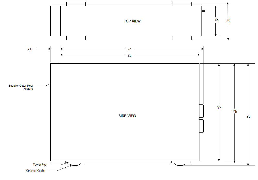
| Xa | Xb | Ya | Yb | Yc | Za (with bezel) | Zb | Zc (Zb + PSU handle) |
|---|---|---|---|---|---|---|---|
| 217.9 mm (8.57 inches) | 304.5 mm (11.99 inches) | 434.5 mm (17.10 inches) | 443.5 mm (17.46 inches) | 471.5 mm (18.56 inches) | 15.9 mm (0.62 inches) | 659.9 mm (25.98 inches) | 692.8 mm (27.27 inches) |
Chassis weight
| System | Maximum weight (with all hard drives/SSDs) |
|---|---|
| 32 x 2.5-inch | 42.36 Kg (93.38 lb) |
| 18 x 3.5-inch | 49.65 Kg (109.45 lb) |
Processor specifications
Supported operating systems
The PowerEdge T640 system supports the following operating systems:
- Canonical Ubuntu LTS
- Citrix XenServer
- Microsoft Windows Server with Hyper-V
- Red Hat Enterprise Linux
- SUSE Linux Enterprise Server
- VMware ESXi
Cooling fan specifications
The cooling fans are integrated into the system to dissipate the heat generated by the functioning of the system. These fans provide cooling for the processors, expansion cards, and memory modules.
Your system supports a total of eight fans, including six hot-swappable fans and two external fans. Two hot-swappable fans are mounted in rear side of the air shroud. The other four hot-swappable (middle) fans are mounted in the fan assembly that is located in the chassis between the hard drive bay and the processors. The two external fans are mounted on the outside of the chassis for GPU configurations. There are two additional fans integrated in the power supplies to cool the power supplies and provide additional cooling for the whole system.
- Fan redundancy
- Fresh air condition
- NVMe/PCIe SSD
- 3.5 inch x 18 hard drives chassis
- Mellanox CX4 DP 100 Gb QSFP NIC (0272F)
- Mellanox CX4 DP 100 Gb NIC (068F2)
- Mellanox CX4 SP 100 Gb NIC (6W1HY)
- Mellanox DP 40 Gb QSFP NIC (C8Y42)
- Intel QP 10 Gb Base-T NIC (K5V44)
- Solarflare Sunspot DP 10Gb NIC (NPHCM)
- Solarflare Nova DP 10Gb NIC (WY7T5)
- Qlogic DP 10Gb V1 NIC (VCXN5)
- GPGPU configurations are not supported at 35deg. C of ambient or above.
- Mellanox 100G NICs are not supported.
PSU specifications
| PSU | Class | Heat dissipation (maximum) | Frequency | Voltage | Current |
|---|---|---|---|---|---|
| 495 W AC | Platinum | 1908 BTU/hr | 50/60 Hz | 100–240 V AC, autoranging | 6.5 A–3 A |
| 750 W AC | Platinum | 2891 BTU/hr | 50/60 Hz | 100–240 V AC, autoranging | 10 A–5 A |
| 750 W AC | Titanium | 2843 BTU/hr | 50/60 Hz | 200–240 V AC, autoranging | 5 A |
| 750 W Mixed Mode HVDC (for China only) | Platinum | 2891 BTU/hr | 50/60 Hz | 100-200 V AC, autoranging | 10 A–5 A |
| Platinum | 2891 BTU/hr | NA | 240 V DC, autoranging | 4.5 A | |
| 750 W Mixed Mode | Platinum | 2891 BTU/hr | 50/60 Hz | 100-200 V AC, autoranging | 10 A–5 A |
| Platinum(For China only) | 2891 BTU/hr | NA | 240 V DC, autoranging | 5 A | |
| 1100 W AC | Platinum | 4100 BTU/hr | 50/60 Hz | 100–240 V AC, autoranging | 12 A–6.5 A |
| 1100 W DC | Gold | 4416 BTU/hr | - | (-48 V to –60 V) DC, autoranging | 32 A |
| 1600 W AC | Platinum | 6000 BTU/hr | 50/60 Hz | 100–240 V AC, autoranging | 10 A |
| 2000 W Mix Mode | Platinum | 7500 BTU/hr | 50/60 Hz | 100–200 V AC, autoranging | 11.5 A |
| 2000 W Mix Mode | Platinum | 7500 BTU/hr | 50/60 Hz | 240 V AC, autoranging | 11.8 A |
| 2400 W AC | Platinum | 9000 BTU/hr | 50/60 Hz | 100–240 V AC, autoranging | 16 A |
System battery specifications
Expansion bus specifications
| PCIe Slot | Processor Connection | Height | Length | Link Width | Slot Width |
|---|---|---|---|---|---|
| 0 (Internal PERC/HBA Slot) | Processor 1 | Full Height | Half Length | x8 | x8 |
| 1 (Gen3) | Processor 1 | Full Height | Full Length | x16 | x16 |
| 2 (Gen3) | Processor 1 | Full Height | Full Length | x4 | x8 |
| 3 (Gen3) | Processor 1 | Full Height | Full Length | x16 | x16 |
| 4 (Gen3) | Processor 2 | Full Height | Half Length | x8 | x8 |
| 5 (Gen3) | Processor 2 | Full Height | Full Length | x4 | x8 |
| 6 (Gen3) | Processor 2 | Full Height | Full Length | x16 | x16 |
| 7 (Gen3) | Processor 2 | Full Height | Full Length | x8 | x8 |
| 8 (Gen3) | Processor 2 | Full Height | Full Length | x16 | x16 |
Memory specifications
| DIMM type | DIMM rank | DIMM capacity | Single processor | Dual processors | ||
|---|---|---|---|---|---|---|
| Minimum RAM | Maximum RAM | Minimum RAM | Maximum RAM | |||
| RDIMM | Single rank | 8 GB | 8 GB | 96 GB | 16 GB | 192 GB |
| Single rank | 16 GB | 16 GB | 192 GB | 32 GB | 384 GB | |
| Dual rank | 32 GB / 64 GB | 32 GB | 384 GB | 64 GB | 768 GB | |
| LRDIMM | Quad rank | 64 GB | 64 GB | 768 GB | 128 GB | 1536 GB |
| Octal rank | 128 GB | 128 GB | 1536 GB | 256 GB | 3072 GB | |
| NVDIMM-N | Single rank | 16 GB | Not supported with single processor | Not supported with single processor | RDIMM: 192 GB | RDIMM: 384 GB |
| NVDIMM-N: 16 GB | NVDIMM-N: 192 GB | |||||
Storage controller specifications
- Internal storage controller cards: PowerEdge RAID Controller (PERC) H330, H730P, H740P, Software RAID (SWRAID) S140, H750
- External PERC (RAID): H840
- 12 Gbps SAS HBA (non-RAID):
- Interal: HBA330 (non-RAID), HBA350i (non-RAID)
- External: 12 Gbps SAS HBA, HBA355e (non-RAID)
- Boot Optimized Storage Subsystem: HWRAID 2 x M.2 SSDs 120GB or 240GB
- Configuration excludes any mixed configurations of HBA330 and HBA350i.
- Configuration excludes any mixed configurations of (H330/H730P/H740P) and H750.
Hard drives
- 8 x 3.5-inch SAS, SATA, Near-Line SAS, SSD
- 16 x 2.5-inch SAS, SATA, Near-Line SAS, SSD, NVMe drives
- 18 x 3.5-inch SAS, SATA, Near-Line SAS, SSD
- 32 x 2.5-inch SAS, SATA, Near-Line SAS, SSD
- SW RAID on 3.5-inch SAS, SATA, Near-Line SAS, SSD
- 8 x NVMe drive
Internal hard drive bay and hot-plug backplane:
- Up to 8 x 3.5-inch SAS, SATA, Near-Line SAS, SSD drives
- Up to 16 x 2.5-inch SAS, SATA, Near-Line SAS, SSD, NVMe drives with optional flex bay
- Up to 18 x 3.5-inch SAS, SATA, Near-Line SAS, SSD drives without optional flex bay
- Up to 32 x 2.5-inch SAS, SATA, Near-Line SAS, SSD drives with optional flex bay
Optical drive
USB ports
| System | Front panel | Back panel | Internal |
|---|---|---|---|
| PowerEdge T640 |
|
Six USB ports
|
One USB 3.0 compliant port |
NIC ports
- Two 10 Gbps
VGA ports
Serial connector
Internal Dual SD Module with vFlash card
- vFlash
- vFlash and IDSDM
Video specifications
The Dell Technologies PowerEdge T640 system supports integrated Matrox G200eW3 graphics controller with 16 MB of video frame buffer.
| Resolution | Refresh rate (Hz) | Color depth (bits) |
|---|---|---|
| 1024 x 768 | 60 | 8, 16, 32 |
| 1280 x 800 | 60 | 8, 16, 32 |
| 1280 x 1024 | 60 | 8, 16, 32 |
| 1360 x 768 | 60 | 8, 16, 32 |
| 1440 x 900 | 60 | 8, 16, 32 |
| 1600 x 900 | 60 | 8, 16, 32 |
| 1600 x 1200 | 60 | 8, 16, 32 |
| 1680 x 1050 | 60 | 8, 16, 32 |
| 1920 x 1080 | 60 | 8, 16, 32 |
| 1920 x 1200 | 60 | 8, 16, 32 |
Environmental specifications
| Temperature | Specifications |
|---|---|
| Storage | –40°C to 65°C (–40°F to 149°F) |
| Continuous operation (for altitude less than 950 m or 3117 ft) | 10°C to 35°C (50°F to 95°F) with no direct sunlight on the equipment. |
| Fresh air | For information about fresh air, see Expanded Operating Temperature section. |
| Maximum temperature gradient (operating and storage) | 20°C/h (68°F/h) |
| Relative humidity | Specifications |
|---|---|
| Storage | 5% to 95% RH with 33°C (91°F) maximum dew point. Atmosphere must be non-condensing at all times. |
| Operating | 10% to 80% relative humidity with 29°C (84.2°F) maximum dew point. |
| Maximum vibration | Specifications |
|---|---|
| Operating | 0.26 Grms at 5 Hz to 350 Hz (all operation orientations). |
| Storage | 1.88 Grms at 10 Hz to 500 Hz for 15 min (all six sides tested). |
| Maximum vibration | Specifications |
|---|---|
| Operating | Six consecutively executed shock pulses in the positive and negative x, y, and z axes |
| Storage | Six consecutively executed shock pulses in the positive and negative x, y, and z axes (one pulse on each side of the system) of 71 G for up to 2 ms. |
| Maximum altitude | Specifications |
|---|---|
| Operating | 30482000 m (10,0006560 ft) |
| Storage | 12,000 m (39,370 ft) |
| Operating temperature de-rating | Specifications |
|---|---|
| Up to 35°C (95°F) | Maximum temperature is reduced by 1°C/300 m (1°F/547 ft) above 950 m (3,117 ft). |
| 35°C to 40°C (95°F to 104°F) | Maximum temperature is reduced by 1°C/175 m (1°F/319 ft) above 950 m (3,117 ft). |
| 40°C to 45°C (104°F to 113°F) | Maximum temperature is reduced by 1°C/125 m (1°F/228 ft) above 950 m (3,117 ft). |
Standard operating temperature
| Standard operating temperature | Specifications |
|---|---|
| Continuous operation (for altitude less than 950 m or 3117 ft) | 10°C to 35°C (50°F to 95°F) with no direct sunlight on the equipment. |
Expanded operating temperature
| Expanded operating temperature | Specifications |
|---|---|
| Continuous operation | 5°C to 40°C at 5% to 85% RH with 29°C dew point. NOTE:Outside the standard
operating temperature (10°C to 35°C), the system can operate continuously
in temperatures as low as 5°C and as high as 40°C. For temperatures between 35°C and 40°C, de-rate maximum allowable temperature by 1°C per 175 m above 950 m (1°F per 319 ft). |
| ≤ 1% of annual operating hours | –5°C to 45°C at 5% to 90% RH with 29°C dew point. NOTE:Outside the standard
operating temperature (10°C to 35°C), the system can operate down
to –5°C or up to 45°C for a maximum of 1% of its annual operating
hours. For temperatures between 40°C and 45°C,de-rate maximum allowable temperature by 1°C per 125 m above 950 m (1°F per 228 ft). |
Expanded operating temperature restrictions and Fresh Air restrictions
- Six hot swappable fans (standard fans) are required.
- Two PSUs in redundancy mode are required, but PSU failure is not supported.
- 3.5-inch x 18 hard drives is not supported.
- NVMe or PCIe SSD is not supported.
- GPGPU is not supported.
- Processor > 165 W is not supported.
- Internal TBU (tape backup drive) is not supported.
- Non-Dell qualified peripheral cards are not supported.
- Peripheral cards consuming greater than 25 W are not supported.
- 128 GB LRDIMM is supported.
- NVDIMM is not supported.
- Mellanox 100 GB, Mellanox Navi DP/SP, Intel FortPond Solarflare Nova, Solarflare Sunspot are not supported.
Particulate and gaseous contamination specifications
| Particulate contamination | Specifications |
|---|---|
| Air filtration | Data center air filtration as defined by ISO Class
8 per ISO 14644-1 with a 95% upper confidence limit. NOTE:The ISO Class 8 condition
applies to data center environments only. This air filtration requirement
does not apply to IT equipment designed to be used outside a data
center, in environments such as an office or factory floor. NOTE:Air entering the data center must have MERV11 or MERV13 filtration. |
| Conductive dust | Air must be free of conductive dust, zinc whiskers,
or other conductive particles. NOTE:This condition applies
to data center and non-data center environments. |
| Corrosive dust |
NOTE:This condition
applies to data center and non-data center environments. |
| Gaseous contamination | Specifications |
|---|---|
| Copper coupon corrosion rate | <300 Å/month per Class G1 as defined by ANSI/ISA71.04-2013. |
| Silver coupon corrosion rate | <200 Å/month as defined by ANSI/ISA71.04-2013. |