Dell EMC PowerEdge T140: технические характеристики и спецификации
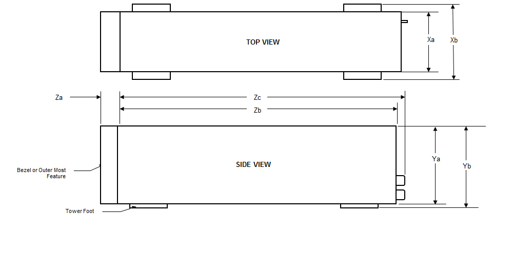
Chassis dimensions
Figure 1. Chassis dimensions
Table 1. Dell EMCPowerEdgeT140system dimensionsThis table provides the dimensions of the Dell EMCPowerEdgeT140system:
Xa
Xb
Ya
Yb
Za
Zb
Zc
175 mm (6.89 inches)
NA
360 mm (14.17 inches)
362.9 mm (14.29 inches)
With bezel: 35.0 mm (1.38 inches)
Without bezel: NA
400.0 mm (15.75 inches)
418.75 mm (16.49 inches)
System weight
Table 1. Dell EMCPowerEdgeT140 system weightSystem weight of
Dell EMCPowerEdgeT140system is 12.18 kilograms with 4 x 3.5-inch drives.
System configuration
Maximum weight (with all drives)
4 x 3.5-inch drives
11.84 kg (26.10 lb)
Processor specifications
Table 1. Dell EMCPowerEdgeT140 processor specificationsThis table provides processor specifications for the
Dell EMCPowerEdgeT140system:
Supported processor
Number of processors supported
Intel Xeon processor E-2200 product family
Intel Core i3 9100 processor
Intel Pentium G5420 processor
Intel Celeron G4930 processor
Intel Xeon processor E-2100 product family
Intel Core i3 8100 processor
Intel Pentium G5500 processor
Intel Celeron G4900 processor
One
PSU specifications
The
Dell EMCPowerEdgeT140 system supports up to one AC cabled power supply unit (PSU).
Table 1. Dell EMCPowerEdgeT140 PSU specificationsThe table lists the power supply specifications.
PSU
Class
Heat dissipation (maximum)
Frequency
Voltage
AC
DC
Current
High line 100–240 V
Low line 100–140 V
365 W AC
Gold
1908 BTU/hr
50/60 Hz
100–240 V AC, autoranging
365 W
N/A
N/A
5 A
NOTE Heat dissipation is calculated using the PSU wattage rating.
NOTE This system is also designed to connect to the IT power systems with a phase-to-phase voltage not exceeding 240 V.
Cooling fan specifications
The Dell EMCPowerEdgeT140system supports the following:
One system cooling fan located at the back of the system.
One processor cooling fan located on the heat sink.
NOTE When selecting
or upgrading the system configuration, to ensure optimum power utilization, verify the system power consumption
with the Dell Energy Smart Solution Advisor available at Dell.com/ESSA.
System battery
specifications
The Dell EMCPowerEdgeT140system supports CR 2032 3.0-V
lithium coin cell system battery.
Expansion card specifications
The Dell EMCPowerEdgeT140 system supports up to four PCI express (PCIe) Generation 3.
Table 1. Expansion card
slots supported on the system boardThis table provides information about the expansion
card slots supported on the PowerEdgeT140 system board.
PCIe slot
Processor Connection
PCIe slot height
PCIe slot length
Slot width
Slot 1 (Gen3)
Processor
Full Height
Half Length
x8 link in x8 slot
Slot 2 (Gen3)
Processor
Full Height
Half Length
x8 link in x16 slot
Slot 3 (Gen3)
Platform Controller Hub
Full Height
Half Length
x1
Slot 4 (Gen3)
Platform Controller Hub
Full Height
Half Length
x4 link in x8 slot
NOTE The expansion cards are not hot swappable.
Memory specifications
The
Dell EMCPowerEdgeT140 system supports the following memory specifications for optimized operation:
Table 1. Memory specificationsThe table below shows the memory specifications for the PowerEdge
T140 system:
DIMM type
DIMM rank
DIMM capacity
Minimum RAM
Maximum RAM
UDIMM
Single rank
8 GB
8 GB
32 GB
16 GB
16 GB
64 GB
Dual rank
8 GB
8 GB
32 GB
16 GB
16 GB
64 GB
Memory module sockets
Speed
Four 288-pin
2666 MT/s
2400 MT/s
2133 MT/s
NOTE 3200 MT/s UDIMM is compatible from BIOS version 2.5.1 but downshift to 2666 MT/s operational speed.
Storage controller specifications
The
Dell EMCPowerEdgeT140 system supports the following controller cards:
Table 1. Dell EMCPowerEdgeT140system controller cardsThis table provides the controller cards supported by
Dell EMCPowerEdgeT140system:
Internal controllers
External controllers
PERC H730P
PERC H330
HBA330
12 Gb/s Ext SAS HBA
HBA355e
Drives
The Dell EMCPowerEdgeT140system supports:
4 x 3.5-inch SAS, SATA drives
NOTE For a system with 4 TB (or more) drive capacity, PERC is required for thermal control.
Optical drives
The Dell EMCPowerEdgeT140system supports the following optical drives.
Table 1. Supported optical drive typeThis table shows the supported optical drive type
Supported drive type
Supported number of drives
Dedicated SATA DVD-ROM
drive or DVD +/-RW drive
One
USB ports specifications
Table 1. Dell EMCPowerEdgeT140system USB port specificationsThe following table shows the USB specifications for the PowerEdge T140 system.
Front panel
Back panel
Internal USB
One USB 3.0-compliant ports
One micro USB 2.0-compliant port for iDRAC Direct
NOTE The micro USB 2.0 compliant
port can only be used as an iDRAC Direct
or a management port.
Two USB 3.0-compliant ports
Four USB 2.0-compliant ports
One internal USB 3.0-compliant port
NIC ports specifications
The Dell EMCPowerEdgeT140 system supports up to two 10/100/1000 Mbps Network Interface Controller (NIC)
ports that are located on the back panel.
Serial connector specifications
The Dell EMCPowerEdgeT140system supports one serial connector on the
back panel, which is a 9-pin connector, Data Terminal Equipment (DTE),
16550-compliant.
VGA ports specification
The Dell EMCPowerEdgeT140system supports one 15-pin VGA port, on the back of the system.
NOTE The front VGA port is available only with the rack configuration.
Video specifications
The
Dell EMCPowerEdgeT140system supports
Matrox G200eW3 graphics card with 16 MB capacity.
Table 1. Supported video resolution optionsThis table describes the supported video resolution options for
Dell EMCPowerEdgeT140system:
Resolution
Refresh rate
Color depth (bits)
640x480
60, 70
8, 16, 24
800x600
60, 75, 85
8, 16, 24
1024x768
60, 75, 85
8, 16, 24
1152x864
60, 75, 85
8, 16, 24
1280x1024
60, 75
8, 16, 24
Environmental
specifications
NOTE For additional information about environmental certifications,
refer to the
Product Environmental Datasheet
located with the Manuals & Documents on www.dell.com/support/home.
Table 1. Temperature
specifications When the system is in continuous operation (for
altitude less than 950 m or 3117 feet), the temperature specification
ranges 10°C to 35°C (50–95°F) with no direct sunlight on
the equipment. When the system is not in operation, the temperature
specification is -40°C to 65°C (-40°F to149°F). For more information
about fresh air, see the Expanded operating temperature section. The
maximum temperature gradient for both operation and nonoperational
systems is 20°C/h (36°F/h). Information about fresh air specification
is described in the Expanded operating temperature section.
Temperature
Specifications
Storage
-40–65°C (-40–149°F)
Continuous operation (for altitude less than 950
m or 3117 ft)
10–35°C (50–95°F) with no direct sunlight
on the equipment
Fresh air
For information about fresh air, see the Expanded
operating temperature section.
Maximum temperature gradient (operating and storage)
20°C/h (68°F/h)
Table 2. Relative humidity
specificationsFor a nonoperational system, the ambient relative
humidity ranges from 5% to 95% with 33°C (91°F) maximum dew point.
Atmosphere must be noncondensing at all times. For an operational
system, the ambient relative humidity ranges from 10% to 80% with
29°C (84.2°F) maximum dew point.
Relative humidity
Specifications
Storage
5% to 95% RH with 33°C (91°F) maximum dew point.
Atmosphere must be noncondensing at all times.
Operating
10% to 80% RH with 29°C (84.2°F) maximum dew point.
Table 3. Maximum vibration
specificationsThe maximum vibration specification of an operational
system is 0.26 Grms at 5 Hz to 350 Hz (all operation orientations).The
maximum vibration specification of a nonoperational system is 1.88
Grms at 10 Hz to 500 Hz for 15
minutes (all six sides tested).
Maximum vibration
Specifications
Operating
0.26 Grms at 5 Hz to 350 Hz (all operation
orientations)
Storage
1.88 Grms at 10 Hz to 500 Hz for 15
minutes (all six sides tested)
Table 4. Maximum shock
pulse specificationsThe maximum shock specification of an operational
system is six consecutively executed shock pulses in the positive
and negative x, y, and z axis of 40 G for up to 2.3 ms. The maximum
shock specification of a nonoperational system is six consecutively
executed shock pulses in the positive and negative x, y, and z axis
(one pulse on each side of the system) of 71 G for up to 2 ms.
Maximum shock pulse
Specifications
Operating
Six consecutively executed shock pulses in the
positive and negative x, y, and z axis of 6 G for up to 11 ms.
Storage
Six consecutively executed shock pulses in the
positive and negative x, y, and z axis (one pulse on each side of
the system) of 71 G for up to 2 ms.
Table 5. Maximum altitude
specificationsThe maximum altitude specification for an operational
system is 3048 m (10,000 ft). The maximum altitude specification for
a nonoperational system is 12,000 m (39,370 ft).
Maximum altitude
Specifications
Operating
3048 m (10,000 ft)
Storage
12,000 m (39,370 ft)
Table 6. Operating temperature
derating specificationsIf the operating temperature of a system is up to
35°C (95°F), the maximum temperature is reduced by 1°C/300 m (1°F/547
feet) above 950 m (3,117 feet). If the operating temperature of a system
is 35°C to 40°C (95°F to 104°F), the maximum temperature is reduced
by 1°C/175 m (1°F/319 feet) above 950 m (3,117 feet). If the operating
temperature of a system is 40°C to 45°C (104°F to 113°F), the
maximum temperature is reduced by 1°C/125 m (1°F/228 feet) above 950
m (3,117 feet).
Operating temperature derating
Specifications
Up to 35°C (95°F)
Maximum temperature is reduced by 1°C/300 m (1°F/547
ft), above 950 m (3,117 ft).
35–40°C (95–104°F)
Maximum temperature is reduced by 1°C/175 m (1°F/319
ft), above 950 m (3,117 ft).
40–45°C (104–113°F)
Maximum temperature is reduced by 1°C/125 m (1°F/228
ft), above 950 m (3,117 ft).
Standard operating
temperature
Table 1. Standard operating
temperature specifications
The standard operating temperature
for altitude less than 950 m or 3117 feet ranges 10°C to 35°C with no
direct sunlight on the equipment.
Standard operating temperature
Specifications
Continuous operation (for altitude less than 950
m or 3117 ft)
10–35°C (50–95°F) with no direct sunlight
on the equipment.
Expanded operating
temperature
Table 1. Expanded operating
temperature specificationsWhen the system is in continuous operation, the
expanded operating temperature ranges 5°C to 40°C at 5% to 85%
RH with 29°C dew point. Outside the standard operating temperature
(10°C to 35°C), the system can operate continuously in temperatures
as low as 5°C and as high as 40°C. For temperatures 35°C to 40°C, derate maximum allowable temperature by 1°C per 175 m above
950 m (1°F per 319 ft). When the system is operating at < 1% of
annual operating hours, the expanded operating temperature is -5°C to 45°C at 5% to 90% RH with 29°C dew point. Outside the standard
operating temperature (10°C to 35°C), the system can operate down
to -5°C or up to 45°C for a maximum of 1% of its annual operating
hours. For temperatures 40°C to 45°C, derate maximum allowable
temperature by 1°C per 125 m above 950 m (1°F per 228 ft).
Expanded operating temperature
Specifications
Continuous operation
5°C–40°C at 5% to 85% RH with 29°C dew point.
NOTE Outside the standard
operating temperature (10°C–35°C), the system can operate continuously
in temperatures as low as 5°C and as high as 40°C.
For temperatures 35°C– 40°C, derate maximum allowable
temperature by 1°C per 175 m (1°F per 319 ft) above 950 m (3,1171
ft).
≤ 1% of annual operating hours
-5°C–45°C at 5% to 90% RH with 29°C dew point.
NOTE Outside the standard
operating temperature (10°C–35°C), the system can operate down
to -5°C or up to 45°C for a maximum of 1% of its annual operating
hours.
For temperatures 40°C– 45°C,
derate maximum allowable temperature by 1°C per 125 m (1°F per 228
ft) above 950 m (3.117 ft).
NOTE When
operating in the expanded temperature range, the performance of the
system may be impacted.
NOTE When operating in the
expanded temperature range, ambient temperature warnings may be reported
on the System Event Log.
Expanded operating
temperature restrictions
Do not perform a cold
startup of the system below 5°C.
The operating temperature
specified is for a maximum altitude of 3048 m (10,000 ft).
One non-redundant power
supply unit is required.
One system
fan required.
Non-Dell qualified peripheral
cards and/or peripheral cards greater than 25 W are not supported.
GPU is not supported.
Tape backup unit is not
supported.
For a system with 4 TB (or more) drive capacity, PERC is required for thermal control.
Particulate
and gaseous contamination specifications
The following
table defines the limitations that help avoid any damages to
the IT equipment and/or, or both failure from particulate and gaseous contamination.
If the levels of particulate or gaseous pollution exceed the specified
limitations and results in equipment damage or failure, you must rectify the environmental conditions. Remediation of environmental
conditions is the responsibility of the customer.
Table 1. Particulate
contamination specifications Air filtration specification: Data center air filtration
as defined by ISO Class 8 per ISO 14644-1 should have a 95% upper
confidence limit. This condition applies only to data center
environments. Air filtration requirements do not apply to IT equipment
designed to be used outside a data center, in environments such as
an office or factory floor. Air entering the data center must
have MERV11 or MERV13 filtration. Conductive dust specification: Air
must be free of conductive dust, zinc whiskers, or other conductive
particles. This condition applies to data center and non-data
center environments. Corrosive dust specification: Air must be free
of corrosive dust. Residual dust present in the air must have a deliquescent
point less than 60% relative humidity. This condition applies
to data center and non-data center environments.
Particulate contamination
Specifications
Air filtration
Data center air filtration as defined
by ISO Class 8 per ISO 14644-1 with a 95% upper confidence limit.
NOTE This condition
applies to data center environments only. Air filtration requirements
do not apply to IT equipment designed to be used outside a data center,
in environments such as an office or factory floor.
NOTE Air entering the data
center must have MERV11 or MERV13 filtration.
Conductive dust
Air must be free of conductive
dust, zinc whiskers, or other conductive particles.
NOTE This condition applies
to data center and non-data center environments.
Corrosive dust
Air must be free of corrosive dust.
Residual dust present in the air must have a deliquescent
point less than 60% relative humidity.
NOTE This condition
applies to data center and non-data center environments.
Table 2. Gaseous contamination
specifications The copper coupon corrosion rate is <300 Å/month
per Class G1 as defined by ANSI/ISA71.04-1985. The silver coupon corrosion
rate is <200 Å/month as defined by AHSRAE TC9.9.
Gaseous contamination
Specifications
Copper Coupon Corrosion
<300 Å/month per Class G1 as defined by ANSI/ISA71.04-1985.
Silver Coupon Corrosion
<200 Å/month as defined by AHSRAE TC9.9.
NOTE Maximum
corrosive contaminant levels measured at ≤50% relative humidity.
Thermal restriction matrix
Table 1. Thermal restrictions
matrixThe following table describes the thermal restriction matrix for the Dell EMCPowerEdgeT140system.