




























Chassis dimensions
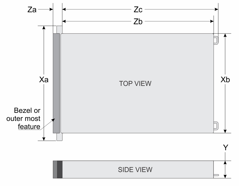
| Drives | Xa | Xb | Y | Za (with bezel) | Za (without bezel) | Zb | Zc |
|---|---|---|---|---|---|---|---|
| All drive configurations | 482.0 mm (18.97 inches) | 434.0 mm (17.08 inches) | 42.8 mm (1.68 inches) | 30.78 mm (1.21 inches) | 29.00 mm (1.14 inches) | 750.57 mm (29.55 inches) | 786.14 mm (30.95 inches) with bezel |
NOTE:Zb is the nominal rear wall external surface where the system board I/O connectors reside.
System weight
| System configuration | Maximum weight (with all drives/SSDs) |
|---|---|
| 8 x 2.5-inch Universal SSDs | 19.96 kg |
| Chassis weight | Description |
|---|---|
| 40–70 lb | Recommend two people to lift |
| 70–120 lb | Recommend three people to lift |
| ≥ 121 lb | Recommend to use a server-lift |
Memory specifications
The
PowerEdge
R4715
system supports the following memory specifications for optimized operation.
| DIMM type | DIMM rank | DIMM capacity | Single processor | |
|---|---|---|---|---|
| Minimum system capacity | Maximum system capacity | |||
| RDIMM | Dual rank | 16 GB | 16 GB | 384 GB |
| 32 GB | 32 GB | 768 GB | ||
| 64 GB | 64 GB | 1.5 TB | ||
| Memory module sockets | Speed |
|---|---|
| 24, DDR5 DIMM slots | 5200 MT/s, 4400 MT/s, 4000 MT/s |
NOTE:Memory DIMM slots are not hot pluggable.
NOTE:The processor may reduce the performance of the rated DIMM speed.
Processor specifications
| Supported processor | Number of processors supported |
|---|---|
| 5th Generation AMD EPYC 9005 Series processor | One |
PSU specifications
The PowerEdgeR4715system supports up to two AC or DC power supply units (PSUs).
| PSU | Class | Heat dissipation (maximum) (BTU/hr) | Frequency (Hz) | Input voltage | Current (A) |
|---|---|---|---|---|---|
| 1100 W AC | Titanium | 4100 | 50/60 | 100-240 Vac | 12-6.1 |
| 1100 W AC | Platinum | 4100 | 50/60 | 100-240 Vac | 12-6.1 |
| 800 W AC | Titanium | 3000 | 50/60 | 100-240 Vac | 9.2-4.5 |
| 800 W AC | Platinum | 3000 | 50/60 | 100-240 Vac | 9.2-4.5 |
NOTE: If a system with AC 1500 W and
1100 W PSUs operates at low line 100-120 Vac, then the power rating per PSU is
derated to 1050 W.
NOTE:The PSUs described above supports Fault Tolerant Redundancy
(FTR), ensuring continuous system operation even if one PSU fails.
| Form factor | Output | Power cord |
|---|---|---|
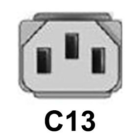
| Redundant 60 mm | 1100 W Titanium mixed mode | C13 |
| Redundant 60 mm | 1100 W Platinum mixed mode | C13 |
| Redundant 60 mm | 800 W Titanium mixed mode | C13 |
| Redundant 60 mm | 800 W Platinum mixed mode | C13 |
Cooling fan specifications
The PowerEdgeR4715system supports up to XX standard (STD) cooling fans.
| Fan type | Abbreviation | Also known as | Label color | Label image |
|---|---|---|---|---|
| Standard (STD) fans | STD | STD | No label | 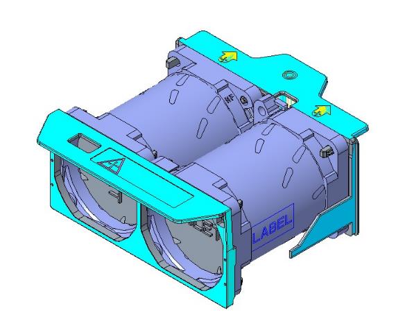 |
| High performance (HPR) silver fans | HPR SLVR | HPR | Silver | 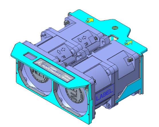 |
Expansion card riser specifications
The
PowerEdge
R4715
system supports up to 3 PCI express (PCIe) slots (3 Gen5 slots) on the system board.
| PCIe slot | Expansion card riser | Processor connection | Height | Length | Slot width |
|---|---|---|---|---|---|
| Slot 1 | Riser 2 | Processor 1 | Low Profile | Full Length | x16 |
| Slot 2 | OCP | Processor 1 | SFF | SFF | x16 |
| Slot 4 | Riser 4 | Processor 1 | Low Profile | Full Length | x16 |
Storage controller specifications
The
PowerEdge
R4715
system supports the following controller cards:
| Supported storage controller cards | |
|---|---|
Internal controllers
|
|
Internal Boot
|
Drives
The PowerEdge
R4715
system supports:
- Up to 4 x 3.5-inch SAS
- Up to 8 x 2.5-inch SAS/SATA
- Up to 8 x U.2 NVMe
NOTE: For more information about how to hot swap NVMe PCIe SSD device, see the
Dell Express Flash NVMe PCIe SSD User's Guide at
Dell Support page.
System battery specifications
The PowerEdge R4715 system uses one CR 2032 3.0-V lithium coin cell battery.
Supported operating systems
The PowerEdge R4715 system supports the following operating systems:
- Canonical Ubuntu Server LTS
- Microsoft Windows Server with Hyper-V
- Red Hat Enterprise Linux
- SUSE Linux Enterprise Server
- VMware ESXi
NIC port specifications
The PowerEdge
R4715
system supports one Datacenter-Secure Control Module
(DC-SCM) Motherboard (LOM) and two optional Open Compute Project (OCP) cards.
| Feature | Specifications |
|---|---|
| Datacenter-Secure Control Module (DC-SCM) | 1 Gb dedicated BMC Ethernet port x1 |
| 2 x OCP NIC 3.0 card | 25 GbE x 2, 25 GbE x 4 |
NOTE:The system allows either DC-SCM or an OCP NIC card
or both to be installed in the system
NOTE:On the MS system board, the supported
OCP NIC PCIe width is x8; when x16 PCIe width is installed, it is downgraded to x8.
NOTE:The system allows either DC-SCM card or MIC card
to be installed in the system.
USB ports specifications
| Front | Rear | Internal (Optional) | |||
|---|---|---|---|---|---|
| USB port type | No. of ports | USB port type | No. of ports | USB port type | No. of ports |
| 1 x USB 2.0 Type-A (optional LCP KVM) | One | USB 3.1-compliant ports | Two | USB 3.1 Type-A | One |
| USB Type C dual-mode host/iDRAC Direct Port | One | ||||
VGA ports specifications
The PowerEdge R4715 system supports DB-15 VGA port on the rear I/O board.
Video specifications
| Resolution | Refresh Rate | Color depth (bits) |
|---|---|---|
| 640 x 480 | 60 Hz | 8, 16, 32 |
| 640 x 480 | 72 Hz | 8, 16, 32 |
| 640 x 480 | 75 Hz | 8, 16, 32 |
| 640 x 480 | 85 Hz | 8, 16, 32 |
| 800 x 600 | 60 Hz | 8, 16, 32 |
| 800 x 600 | 72 Hz | 8, 16, 32 |
| 800 x 600 | 75 Hz | 8, 16, 32 |
| 800 x 600 | 85 Hz | 8, 16, 32 |
| 1024 x 768 | 60 Hz | 8, 16, 32 |
| 1024 x 768 | 72 Hz | 8, 16, 32 |
| 1024 x 768 | 75 Hz | 8, 16, 32 |
| 1024 x 768 | 85 Hz | 8, 16, 32 |
| 1152 x 864 | 75 Hz | 8, 16, 32 |
| 1280 x 800 | 60 Hz | 8, 16, 32 |
| 1280 x 800 | 75 Hz | 8, 16, 32 |
| 1280 x 1024 | 60 Hz | 8, 16, 32 |
| 1280 x 1024 | 75 Hz | 8, 16, 32 |
| 1280 x 1024 | 85 Hz | 8, 16, 32 |
| 1360 x 768 | 60 Hz | 8, 16, 32 |
| 1440 x 900 | 60 Hz | 8, 16, 32 |
| 1440 x 900 | 60 Hz (RB) | 8, 16, 32 |
| 1440 x 900 | 75 Hz | 8, 16, 32 |
| 1440 x 900 | 85 Hz | 8, 16, 32 |
| 1600 x 900 | 60 Hz (RB) | 8, 16, 32 |
| 1600x 900 | 60 Hz (RB) | 8, 16, 32 |
| 1600 x 1200 | 60 Hz | 8, 16, 32 |
| 1600 x 1200 | 60 Hz (RB) | 8, 16, 32 |
| 1600 x 1200 | 65 Hz | 8, 16, 32 |
| 1600 x 1200 | 70 Hz | 8, 16, 32 |
| 1600 x 1200 | 75 Hz | 8, 16, 32 |
| 1600 x 1200 | 85 Hz | 8, 16, 32 |
| 1680 x 1050 | 60 Hz (RB) | 8, 16, 32 |
| 1680 x 1050 | 60 Hz | 8, 16, 32 |
| 1680 x 1050 | 75 Hz | 8, 16, 32 |
| 1680 x 1050 | 85 Hz | 8, 16, 32 |
| 1920 x 1080 | 60 Hz | 8, 16, 32 |
| 1920 x 1080 | 60 Hz (RB) | 8, 16, 32 |
| 1920 x 1200 | 60 Hz | 8, 16, 32 |
| 1920 x 1200 | 60 Hz (RB) | 8, 16, 32 |
| 1920 x 1200 | 75 Hz | 8, 16, 32 |
| 1920 x 1200 | 85 Hz | 8, 16, 32 |
NOTE:(RB) - Reduced Blanking for Digital Displays requiring less blank time. This was introduced for Signal Integrity improvements by reducing Pixel Clock rates for VGA- Analog input devices.
Environmental specifications
NOTE:For additional information about environmental certifications, refer to the
Product Environmental Datasheet located with the
Manuals & Documents on
Dell Support.
| Operating Ranges | Allowable continuous operations |
|---|---|
| Temperature range for altitudes <= 900 m (<= 2953 ft) | 10–35°C (50–95°F) with no direct sunlight on the equipment |
| Humidity percent range (non-condensing at all times) | 8% RH with -12°C minimum dew point to 80% RH with 21°C (69.8°F) maximum dew point |
| Operational altitude de-rating | Maximum temperature is reduced by 1°C/300 m (33.8°F/984 Ft) above 900 m (2953 Ft) |
| Operating Ranges | Allowable continuous operations |
|---|---|
| Temperature range for altitudes <= 900 m (<= 2953 ft) | 5–40°C (41–104°F) with no direct sunlight on the equipment |
| Humidity percent range (non-condensing at all times) | 8% RH with -12°C minimum dew point to 85% RH with 24°C (75.2°F) maximum dew point |
| Operational altitude de-rating | Maximum temperature is reduced by 1°C/175 m (33.8°F/574 Ft) above 900 m (2953 Ft) |
| Operating Ranges | Allowable continuous operations |
|---|---|
| Temperature range for altitudes <= 900 m (<= 2953 ft) | 5–45°C (41–113°F) with no direct sunlight on the equipment |
| Humidity percent range (non-condensing at all times) | 8% RH with -12°C minimum dew point to 90% RH with 24°C (75.2°F) maximum dew point |
| Operational altitude de-rating | Maximum temperature is reduced by 1°C/125 m (33.8°F/410 Ft) above 900 m (2953 Ft) |
| Operating Ranges | Allowable continuous operations |
|---|---|
| Maximum temperature gradient (applies to both operation and non-operation) | 20°C in an hour* (36°F in an hour) and 5°C in 15 minutes (41°F in 15 minutes), 5°C in an hour* (41°F in an hour) for tape
NOTE:* - Per ASHRAE thermal guidelines for tape hardware, these are not instantaneous rates of temperature change.
|
| Non-operational temperature limits | -40 to 65°C (-104 to 149°F) |
| Non-operational humidity limits | 5% to 95% RH with 27°C (80.6°F) maximum dew point |
| Maximum non-operational altitude | 12,000 meters (39,370 feet) |
| Maximum operational altitude | 3,048 meters (10,000 feet) |
| Maximum vibration | Specifications |
|---|---|
| Operating | 0.21 Grms at 5 Hz to 500 Hz (all operation orientations) |
| Storage | 1.38 Grms at 7 Hz to 250 Hz for 15 minutes (all six sides tested) |
| Maximum shock pulse | Specifications |
|---|---|
| Operating | Six consecutively executed shock pulses in the positive and negative x, y, and z axis of 6 G for up to 11 ms. |
| Storage | Six consecutively executed shock pulses in the positive and negative x, y, and z axis (one pulse on each side of the system) of 71 G for up to 2 ms. |
Thermal restriction matrix
| Label | Description |
|---|---|
| STD | Standard |
| HPR (Silver) | High performance Silver (HPR SLVR) fan |
| HSK | Heat sink |
| LP | Low profile |
| FH | Full height |
| Heat sink | Processor TDP |
|---|---|
| C-type HSK | Supports all TDP (system should be installed with GPU/FGPA/long PCIe cards) |
| Supported at 35°C | R4715 air cooling | |||
|---|---|---|---|---|
| Max 30°C support | ||||
| Configuration | 8 x 2.5-inch (smart flow) | 4 x 3.5-inch | ||
| Rear storage | No rear drives | No rear drives | ||
| CPU TDP/cTDP | Processor | cTDP | ||
| 9015 | 155 W | C-type HSK, STD fan | C-type HSK, HPR silver fan | |
| 9135 | 240 W | C-type HSK, STD fan | C-type HSK, HPR silver fan | |
| 9255 | 240 W | C-type HSK, STD fan | C-type HSK, HPR silver fan | |
| 9335 | 240 W | C-type HSK, STD fan | C-type HSK, HPR silver fan | |
| Memory | 16 GB RDIMM | STD fan | HPR silver fan | |
| 32 GB RDIMM | STD fan | HPR silver fan | ||
| 64 GB RDIMM | STD fan | HPR silver fan | ||
Thermal air restrictions
Fresh air environment
- Two PSUs are required in redundant mode, however a single PSU failure is not supported.
- PCIe SSD is not supported.
- 128 GB or greater capacity DIMMs are not supported.
- GPU and FPGA are not supported.
- CPU TDP greater than 240 W are not supported.
- Rear drives are not supported.
- Non-Dell qualified peripheral cards and/or peripheral cards greater than 25 W are not supported.
| ASHRAE | ASHRAE A3/40°C (104°F) | A4/45°C (113°F) |
|---|---|---|
| Front storage | Support at 2.5-inch SATA/SAS x 8 configuration only | |
| Fan type | HPR silver fan are required | |
| CPU | CPU TDP > 240 W are not supported | TBD |
| Memory | 128 GB and higher capacity RDIMMs are not supported | |
| PCIe card | Non-Dell qualified peripheral cards and consuming power greater than 25 W are not supported | |
| GPU | GPU cards are not supported | |
| Rear storage | Not supported | |
| OCP | Support with 85°C active optic cable | TBD |
| PSU | Two PSUs are required in redundant mode. System performance may be reduced in the event of a PSU failure | |
| BOSS | Boot Optimized Storage Subsystem (BOSS-N1 DC-MHS) | |