




























Chassis dimensions
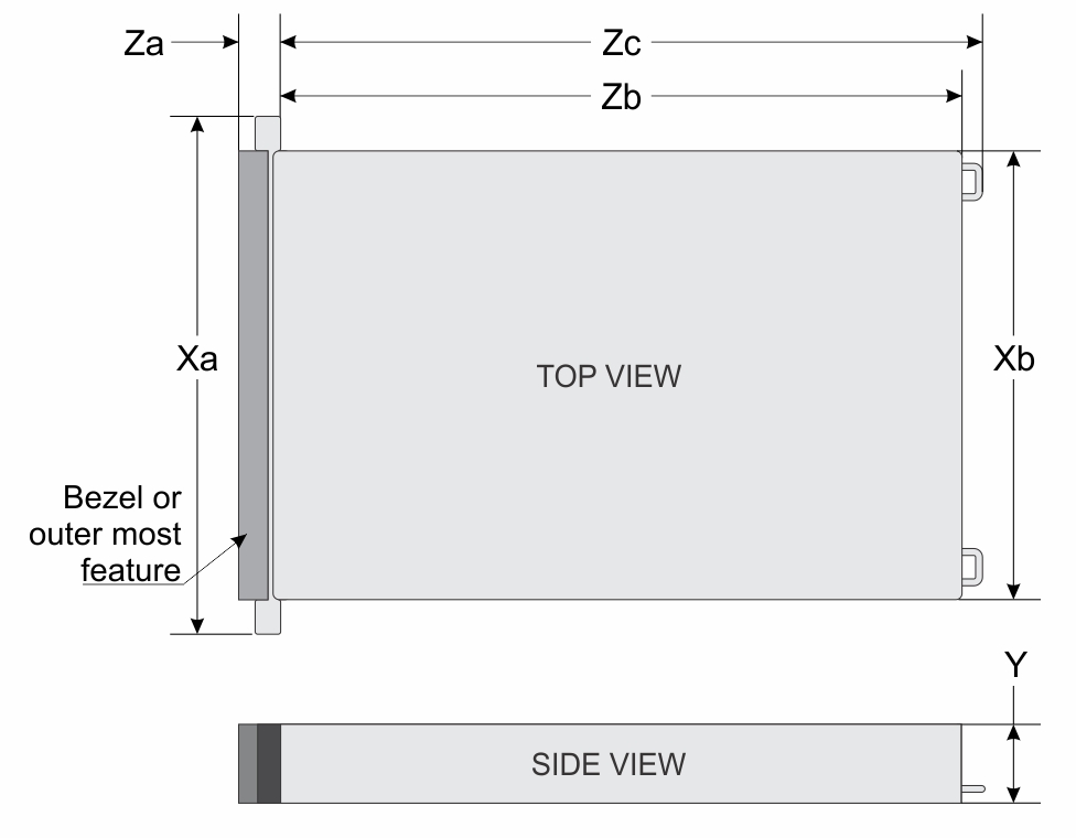
| Drives | Xa | Xb | Y | Za | Zb | Zc |
|---|---|---|---|---|---|---|
| 8 x E3.S EDSFF drives Front I/O configuration | 482.0 mm (19 inches) | 434.0 mm (17.1 inches) | 42.8 mm (1.69 inches) | 43.3 mm (1.7 inches) | 750.57 mm (29.55 inches)Ear to rear wall | 786.141 mm (30.95 inches)Ear to PSU handle |
8 x 2.5-inch drives 10 x 2.5-inch drives 4 x 3.5-inch drives 16 x E3.S EDSFF drives | 482.0 mm (19 inches) | 434.0 mm (17.1 inches) | 42.8 mm (1.69 inches) | With bezel 30.78 mm (1.21 inches)Without bezel 29.0 mm (1.14inches) | 750.57 mm (29.55 inches)Ear to rear wall | 786.141 mm (30.95 inches)Ear to PSU handle |
System weight
| System configuration | Maximum weight (with all drives/SSDs) |
|---|---|
| 8 x E3.S EDSFF | 19.11 kg (42.13 lb) |
| 16 x E3.S EDSFF | 17.66 kg (38.93 lb) |
| 8 x 2.5-inch SATA | 17.03 kg (37.54 lb) |
| 10 x 2.5 - inch SATA | 17.53 kg (38.64 lb) |
| 4 x 3.5 - inch SATA | 18.78 kg (41.40 lb) |
| Chassis weight | Description |
|---|---|
| 40–70 lbs | Recommend two people to lift. |
| 70–120 lbs | Recommend three people to lift. |
| ≥ 121 lbs | Recommend to use a server-lift. |
Processor specifications
| Supported processor | Number of processors supported |
|---|---|
| Intel® Xeon 6 processor | One
NOTE: R470 supports both Intel® E-
Core and Intel® P-Core processors |
| Processors | IDRAC | BIOS | FPGA |
|---|---|---|---|
| Intel® Xeon® 6 E-core processor | 1.10.17.00 | 1.1.3 | 106.102.000 |
| Intel® Xeon® 6 P-core processor | 1.20.25.00 | 1.2.6 | 107.102.000 |
PSU specifications
The PowerEdgeR470system supports up to two AC or DC power supply units (PSUs).
| PSU | Class | Heat dissipation (maximum) (BTU/hr) | Frequency (Hz) | AC Voltage | DC Voltage | Current (A) | ||||
|---|---|---|---|---|---|---|---|---|---|---|
| 200—240 V | 100—120 V | 277 V | 240 V | - (48—60) V | 336 V | |||||
| 800 W mixed mode | Platinum | 3000 | 50/60 | 800 W | 800 W | N/A | N/A | N/A | N/A | 9.2—4.5 A |
| Titanium | 3000 | 50/60 | 800 W | 800 W | N/A | N/A | N/A | N/A | 9.2—4.5 A | |
| N/A | 3000 | N/A | N/A | N/A | N/A | 800 W | N/A | N/A | 3.7 A | |
| 1100 W | Titanium | 4100 | 50/60 | 1100 W | 1050 W | N/A | N/A | N/A | N/A | 12—6.1 A |
| Platinum | 4100 | 50/60 | 1100 W | 1050 W | N/A | N/A | N/A | N/A | 12—6.1 A | |
| N/A | 4100 | N/A | N/A | N/A | N/A | 1100 W | N/A | N/A | 5.1 A | |
| 1400 W -48 VDC | Titanium | 5310 | N/A | N/A | N/A | N/A | N/A | 1400 W | N/A | 33 A |
| 1500 W 227 VAC | Titanium | 5625 | 50/60 | N/A | N/A | N/A | 1500 W | N/A | N/A | 6.1 A |
| N/A | 5625 | N/A | N/A | N/A | N/A | N/A | N/A | 1500 W | 4.91 A | |
| 1500 W mixed mode | Titanium | 5625 | 50/60 | 1500 W | 1050 W | N/A | N/A | N/A | N/A | 12—8.2 A |
| N/A | 5625 | N/A | N/A | N/A | N/A | 1500 W | N/A | N/A | 6.8 A | |
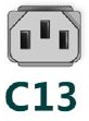
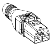
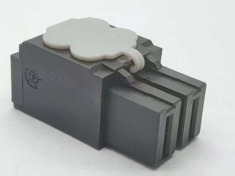
| Form factor | Output | Power cable |
|---|---|---|
| Redundant 60 mm | 800 W mixed mode | C13 |
| 1100 W mixed mode | C13 | |
| 1400 W -48v DC | LOTES APOWA048 | |
| 1500 W mixed mode | C13 | |
| 1500w 277v | APP2006G1/2006G3 |
Cooling fan specifications
The PowerEdgeR470system supports up to four sets of 2 fan module standard (STD) cooling fans or high performance (HPR) silver cooling fans .
| Fan type | Abbreviation | Also known as | Label color | Label image |
|---|---|---|---|---|
| Standard (STD) fans | STD | STD | No label | 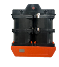 |
| High performance (HPR) silver fans | HPR SLVR | HPR | Silver | 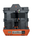 |
Supported operating systems
The PowerEdge R470 system supports the following operating systems:
- Canonical Ubuntu Server LTS
- RedHat Enterprise Linux
- SUSE Linux Enterprise Server
- VMware ESXi
- Windows Server
- Windows Server Datacenter
System battery specifications
The PowerEdge R470 system uses one CR 2032 3.0-V lithium coin cell battery.
Expansion card riser specifications
| PCIe slot | Expansion card riser | Processor connection | Height | Length | Slot width |
|---|---|---|---|---|---|
| Slot 3 (Optional rear BOSS-N1 ) | N/A | Processor 0 | N/A | N/A | x4 |
| Slot 5 (Optional OCP) | N/A | Processor 0 | N/A | N/A | x16 |
| Slot 31 | RF1d (front OCP) | Processor 0 | N/A | N/A | x16 |
| Slot 32 | RF1d (front OCP) | Processor 0 | N/A | N/A | x16 |
| Slot 34 (Optional front BOSS-N1) | N/A | Processor 0 | N/A | N/A | x4 |
| Slot 1 | R2q | Processor 0 | Full Height | Half Length | x16 |
| Slot 4 | R4b | Processor 0 | Full Height | Half Length | x16 |
| Slot 34 (Optional front BOSS-N1 ) | N/A | Processor 0 | N/A | N/A | x4 |
| Slot 1 | R2k | Processor 0 | Low profile | Half Length | x16 |
| Slot 2 (Flop OCP) | R2k | Processor 0 | N/A | N/A | x16 |
| Slot 4 | R4a | Processor 0 | Low Profile | Half Length | x16 |
| Slot 1 | R2v | Processor 0 | Low Profile | Half Length | x16 |
| Slot 2 (Flop OCP) | R2v | Processor 0 | N/A | N/A | x16 |
Memory specifications
| DIMM type | Rank | Capacity | Single Processor | |||
|---|---|---|---|---|---|---|
| Intel® Xeon 6 E- core processor | Intel® Xeon 6 P- core processor | |||||
| Minimum system capacity | Maximum system capacity | Minimum system capacity | Maximum system capacity | |||
| RDIMM | 1 R | 16 GB | N/A | N/A | 16 GB | 128 GB |
| 2 R | 32 GB | 32 GB | 256 GB | 32 GB | 512 GB | |
| 64 GB | 512 GB | 1 TB | 256 GB | 1 TB | ||
| 96 GB | N/A | N/A | 768 GB | 1.5 TB | ||
| 128 GB | N/A | N/A | 1 TB | 2 TB | ||
| 8 R | 256 GB | N/A | N/A | 4 TB | 4 TB | |
| Memory module sockets | Speed |
|---|---|
| 16, 288-pin | 6400 MT/s (1DPC)
5200 MT/s (2 DPC) |
Storage controller specifications
| Supported storage controller cards |
|---|
Internal controllers
|
External controllers
|
Internal boot
|
Software RAID
|
Drives
- 8 x EDSFF E3.S hot-swappable NVMe drives.
- Up to 16 x EDSFF E3.S hot-swappable NVMe drives.
- 8 x 2.5-inch hot-swappable SATA drives.
- 10 x 2.5-inch hot-swappable SATA drives with four universal ports.
- 4 x 3.5-inch hot-swappable SATA drives with 2 x EDSFF E3.S hot-swappable rear drives.
GPU Specifications
- Up to four NVIDIA L4 24 GB 72 W Low Profile or Full Height card.
DPU Specifications
The PowerEdge R470 platform accommodates Data Processing Units (DPUs). These units are system-on-chip solutions that combine ARM cores, high-performance NICs, and programmable acceleration engines to offload and accelerate data center infrastructure services.
| Feature | Specifications |
|---|---|
| Model | NVIDIA BlueField-3 B3220 |
| Type | Data Processing Units (DPU) |
| Networking | 2 x 200 GbE |
| Form Factor | FHHL |
| Interface | PCIe Gen5 x16 |
| Power Consumption | 150 W |
| Compatible Risers | RC2 (Slot 31), RC4 (Slot 1), RC5 (Slot 1), RC6 (Slot 1) |
NIC port specifications
| Feature | Specifications |
|---|---|
| Datacenter-Secure Control Module (DC-SCM) | 1GB x 1 |
| OCP 3.0 card | 25 GbE x 2 , 25 GbE x 4 ,100 GbE x 2 |
USB ports specifications
| Front | Rear | Internal | |||
|---|---|---|---|---|---|
| USB port type | No. of ports | USB port type | No. of ports | USB port type | No. of ports |
| USB 2.0-compliant port | One (Optional) | USB 3.1- compliant ports | Two | Internal USB 3.1- compliant port | One |
| Type-C USB 2.0-compliant port dual-mode host/iDRAC Direct port | One | ||||
Serial connector specifications
The PowerEdge R470 system supports one optional card type connector, which is a 9 - pin connector, Data Terminal Equipment (DTE), 16550-compliant .
The optional serial connector card is available only in front I/O configuration.
Top USB port on DC-SCM supports external DB9 Dongle.
Video ports specifications
The PowerEdge R470 system supports one DB-15 VGA port (optional) on the rear I/O board and one Mini Display (mDP) port (optional) on the Left Control Panel (LCP) .
Video specifications
| Resolution | Refresh rate (Hz) | Color depth (bits) |
|---|---|---|
| 1024 x 768 | 60 | 8, 16, 32 |
| 1280 x 800 | 60 | 8, 16, 32 |
| 1280 x 1024 | 60 | 8, 16, 32 |
| 1360 x 768 | 60 | 8, 16, 32 |
| 1440 x 900 | 60 | 8, 16, 32 |
| 1600 x 900 | 60 | 8, 16, 32 |
| 1600 x 1200 | 60 | 8, 16, 32 |
| 1680 x 1050 | 60 | 8, 16, 32 |
| 1920 x 1080 | 60 | 8, 16, 32 |
| 1920 x 1200 | 60 | 8, 16, 32 |
Environmental specifications
| Temperature | Allowable continuous operations |
|---|---|
| Temperature range for altitudes <= 900 m (<= 2953 ft) | 10–35°C (50–95°F) with no direct sunlight on the equipment |
| Humidity percent range (non-condensing at all times) | 8% RH with -12°C minimum dew point to 80% RH with 21°C (69.8°F) maximum dew point |
| Operational altitude de-rating | Maximum temperature is reduced by 1°C/300 m (1.8°F/984 Ft) above 900 m (2953 Ft) |
| Temperature | Allowable continuous operations |
|---|---|
| Temperature range for altitudes <= 900 m (<= 2953 ft) | 5–40°C (41–104°F) with no direct sunlight on the equipment |
| Humidity percent range (non-condensing at all times) | 8% RH with -12°C minimum dew point to 85% RH with 24°C (75.2°F) maximum dew point |
| Operational altitude de-rating | Maximum temperature is reduced by 1°C/175 m (1.8°F/984 Ft) above 900 m (2953 Ft) |
| Temperature | Allowable continuous operations |
|---|---|
| Temperature range for altitudes <= 900 m (<= 2953 ft) | 5–45°C (41–113°F) with no direct sunlight on the equipment |
| Humidity percent range (non-condensing at all times) | 8% RH with -12°C minimum dew point to 90% RH with 24°C (75.2°F) maximum dew point |
| Operational altitude de-rating | Maximum temperature is reduced by 1°C/125 m (1.8°F/984 Ft) above 900 m (2953 Ft) |
| Temperature | Allowable continuous operations |
|---|---|
| Maximum temperature gradient (applies to both operation and non-operation) | 20°C in an hour* (36°F in an hour) and 5°C in 15 minutes (41°F in 15 minutes), 5°C in an hour* (9°F in an hour) for tape
NOTE:* - Per ASHRAE thermal guidelines for tape hardware, these are not instantaneous rates of temperature change.
|
| Non-operational temperature limits | -40 to 65°C (-40 to 149°F) |
| Non-operational humidity limits | 5% to 95% RH with 27°C (80.6°F) maximum dew point |
| Maximum non-operational altitude | 12,000 meters (39,370 feet) |
| Maximum operational altitude | 3,048 meters (10,000 feet) |
| Maximum vibration | Specifications |
|---|---|
| Operating | 0.21 Grms at 5 Hz to 500 Hz for 10min (all x, y, and z axes) |
| Storage | 1.38 Grms at 7 Hz to 250 Hz for 15 minutes (all six sides tested) |
| Maximum shock pulse | Specifications |
|---|---|
| Operating | Six consecutively executed shock pulses in the positive and negative x, y, and z axis of 6 G for up to 11 ms. |
| Storage | Six consecutively executed shock pulses in the positive and negative x, y, and z axis (one pulse on each side of the system) of 71 G for up to 2 ms. |
Particulate and gaseous contamination specifications
The following table defines the limitations that help avoid any equipment damage or failure from particulates and gaseous contamination. If the levels of particulates or gaseous pollution exceed the specified limitations and result in equipment damage or failure, you must rectify the environmental conditions. Remediation of environmental conditions is the responsibility of the customer.
| Particulate contamination | Specifications |
|---|---|
| Air filtration: Conventional Data Center only | Data center air filtration as defined by ISO Class 8 per ISO 14644-1 with a 95% upper confidence limit
NOTE: Filtering room air with a MERV8 filter, as specified in ANSI/ASHRAE Standard 127, is a recommended method for achieving the necessary environmental conditions.
NOTE:Air entering the data center must have MERV11 or MERV13 filtration.
NOTE:This condition applies to data center environments only. Air filtration requirements do not apply to IT equipment designed to be used outside a data center, in environments such as an office or factory floor.
|
| Walk-Up Edge Data Center or Cabinet (sealed, closed loop environment) | Filtration is not required for cabinets that are anticipated to be opened six times or less per year. Class 8 per ISO 1466-1 filtration as defined above is required otherwise.
NOTE: In environments commonly above ISA-71 Class G1 or that may have known challenges, special filters may be required.
|
| Conductive dust: data center and non-data center environments | Air must be free of conductive dust, zinc whiskers, or other conductive particles.
NOTE: Conductive dust, which can interfere with equipment operation, can originate from various sources, including manufacturing processes and zinc whiskers that may develop on the plating of raised floor tiles.
NOTE:This condition applies to data center and non-data center environments.
|
| Corrosive dust: data center and non-data center environments |
NOTE:This condition applies to data center and non-data center environments.
|
| Gaseous contamination | Specifications | Notes |
|---|---|---|
| Copper coupon corrosion rate | ISA-71 Class G1: <300 Å/month | Per ANSI/ISA71.04 |
| Silver coupon corrosion rate | ISA-71 Class G1: <200 Å/month | Per ANSI/ISA71.04 |
Thermal restriction matrix
| Label | Description |
|---|---|
| STD | Standard |
| HPR (Silver) | High performance Silver (HPR SLVR) fan |
| HPR (Gold) | High performance Gold (HPR GOLD) fan |
| HSK | Heat sink |
| LP | Low profile |
| FH | Full height |
| DLC | Direct Liquid Cooling |
| Heat sink | Processor TDP |
|---|---|
| Extend HSK | <=250 W |
| Remote HSK | >250 W |
| Configuration | 8 x EDSFF E3.S NVMe | 16 x EDSFF E3.S NVMe | 8 x 2.5 inch SAS/SATA/NVMe | 10 x 2.5 inch SAS/SATA | 4 x 3.5 inch SAS/SATA with rear 2 x EDSFF E3.S NVMe | Ambient temperature | ||
|---|---|---|---|---|---|---|---|---|
| Storage configuration number | C01-1/2/3 , C06-01 | C05-01 | C02-1/2/3/5/6 | C04-1/2 | C03-01 | |||
| Riser configuration | RC-2/3/4/56/7 | RC-7 | RC-0/6/8 | RC-6/7 | RC-1 | |||
| Air shroud type | EXT/Remote | EXT/Remote | EXT/Remote | EXT/Remote | EXT/Remote | |||
| Processor | TDP | Cores | Fan | |||||
| 6780E | 330 W | 144 | HPR SLVR | HPR SLVR | HPR SLVR | HPR SLVR | HPR SLVR | 35°C |
| 6766E | 250 W | 144 | STD | STD | STD | HPR SLVR | STD | 35°C |
| 6756E | 225 W | 128 | STD | STD | STD | STD | STD | 35°C |
| 6746E | 250 W | 112 | STD | STD | STD | HPR SLVR | STD | 35°C |
| 6740E | 250 W | 96 | STD | STD | STD | HPR SLVR | STD | 35°C |
| 6731E | 250 W | 96 | STD | STD | STD | HPR SLVR | STD | 35°C |
| 6710E | 205 W | 64 | STD | STD | STD | STD | STD | 35°C |
| 6787P | 350 W | 86 | HPR SLVR | HPR SLVR | HPR SLVR | HPR SLVR | HPR SLVR | 35°C |
| 6767P | 350 W | 64 | HPR SLVR | HPR SLVR | HPR SLVR | HPR SLVR | HPR SLVR | 35°C |
| 6747P | 330 W | 48 | HPR SLVR | HPR SLVR | HPR SLVR | HPR SLVR | HPR SLVR | 35°C |
| 6737P | 270 W | 32 | HPR SLVR | HPR SLVR | HPR SLVR | HPR SLVR | HPR SLVR | 35°C |
| 6730P | 250 W | 32 | STD | STD | STD | HPR SLVR | STD | 35°C |
| 6527P | 255 W | 24 | HPR SLVR | HPR SLVR | HPR SLVR | HPR SLVR | HPR SLVR | 35°C |
| 6724P | 210 W | 16 | STD | STD | STD | STD | STD | 35°C |
| 6517P | 190 W | 16 | STD | STD | STD | STD | STD | 35°C |
| 6505P | 150 W | 12 | STD | STD | STD | STD | STD | 35°C |
| 6507P | 150 W | 8 | STD | STD | STD | STD | STD | 35°C |
| 6781P | 350 W | 80 | HPR SLVR | HPR SLVR | HPR SLVR | HPR SLVR | HPR SLVR | 35°C |
| 6761P | 350 W | 64 | HPR SLVR | HPR SLVR | HPR SLVR | HPR SLVR | HPR SLVR | 35°C |
| 6741P | 300 W | 48 | HPR SLVR | HPR SLVR | HPR SLVR | HPR SLVR | HPR SLVR | 35°C |
| 6731P | 245 W | 32 | STD | STD | STD | STD | STD | 35°C |
| 6521P | 225 W | 24 | STD | STD | STD | STD | STD | 35°C |
| 6511P | 150 W | 16 | STD | STD | STD | STD | STD | 35°C |
| Configuration | 8 x EDSFF E3.S NVMe | 16 x EDSFF E3.S NVMe | 8 x 2.5 inch SAS/SATA/NVMe | 10 x 2.5 inch SAS/SATA | 4 x 3.5 inch SAS/SATA with rear 2 x EDSFF E3.S NVMe | Ambient temperature | ||
|---|---|---|---|---|---|---|---|---|
| Storage configuration number | C01-1/2/3 , C06-01 | C05-01 | C02-1/2/3/5/6 | C04-1/2 | C03-01 | |||
| Riser configuration | RC-2/3/4/56/7 | RC-7 | RC-0/6/8 | RC-6/7 | RC-1 | |||
| Air shroud type | EXT/Remote | EXT/Remote | EXT/Remote | EXT/Remote | EXT/Remote | |||
| Processor | TDP | Cores | Fan | |||||
| 6780E | 330 W | 144 | HPR SLVR | HPR SLVR | HPR SLVR | HPR SLVR | HPR SLVR | 35°C |
| 6766E | 250 W | 144 | STD | STD | STD | HPR SLVR | STD | 35°C |
| 6756E | 225 W | 128 | STD | STD | STD | STD | STD | 35°C |
| 6746E | 250 W | 112 | STD | STD | STD | HPR SLVR | STD | 35°C |
| 6740E | 250 W | 96 | STD | STD | STD | HPR SLVR | STD | 35°C |
| 6731E | 250 W | 96 | STD | STD | STD | HPR SLVR | STD | 35°C |
| 6710E | 205 W | 64 | STD | STD | STD | STD | STD | 35°C |
| 6787P | 350 W | 86 | HPR SLVR | HPR SLVR | HPR SLVR | HPR SLVR | HPR SLVR | 35°C |
| 6767P | 350 W | 64 | HPR SLVR | HPR SLVR | HPR SLVR | HPR SLVR | HPR SLVR | 35°C |
| 6747P | 330 W | 48 | HPR SLVR | HPR SLVR | HPR SLVR | HPR SLVR | HPR SLVR | 35°C |
| 6737P | 270 W | 32 | HPR SLVR | HPR SLVR | HPR SLVR | HPR SLVR | HPR SLVR | 35°C |
| 6730P | 250 W | 32 | STD | STD | STD | HPR SLVR | STD | 35°C |
| 6527P | 255 W | 24 | HPR SLVR | HPR SLVR | HPR SLVR | HPR SLVR | HPR SLVR | 35°C |
| 6724P | 210 W | 16 | STD | STD | STD | STD | STD | 35°C |
| 6517P | 190 W | 16 | STD | STD | STD | STD | STD | 35°C |
| 6505P | 150 W | 12 | STD | STD | STD | STD | STD | 35°C |
| 6507P | 150 W | 8 | STD | STD | STD | STD | STD | 35°C |
| 6781P | 350 W | 80 | HPR SLVR | HPR SLVR | HPR SLVR | HPR SLVR | HPR SLVR | 35°C |
| 6761P | 350 W | 64 | HPR SLVR | HPR SLVR | HPR SLVR | HPR SLVR | HPR SLVR | 35°C |
| 6741P | 300 W | 48 | HPR SLVR | HPR SLVR | HPR SLVR | HPR SLVR | HPR SLVR | 35°C |
| 6731P | 245 W | 32 | STD | STD | STD | STD | STD | 35°C |
| 6521P | 225 W | 24 | STD | STD | STD | STD | STD | 35°C |
| 6511P | 150 W | 16 | STD | STD | STD | STD | STD | 35°C |
Thermal air restrictions
ASHRAE A3 environment
8 x EDSFF E3.S Configuration (Cold Aisle Capable Front I/O)
- CPU > 225 W is not supported.
- 128G or greater capacity RDIMMs are not supported.
- GPU cards are not supported.
- DPU is not supported.
- Two PSUs are required in redundant mode. System performance may be reduced in the event of a PSU failure.
- Non-Dell qualified peripheral cards and/or peripheral cards greater than 25 W are not supported.
- 85 C active optics or DAC is required.
16 x EDSFF E3.S Configuration
- CPU > 225 W is not supported.
- 128G or greater capacity RDIMMs are not supported.
- GPU cards are not supported.
- DPU is not supported.
- Two PSUs are required in redundant mode. System performance may be reduced in the event of a PSU failure.
- Non-Dell qualified peripheral cards and/or peripheral cards greater than 25 W are not supported.
- 85 C active optics or DAC is required.
8 x 2.5-inch Configuration SAS/SATA; NVMe RAID/direct
- CPU > 225 W is not supported.
- 128G or greater capacity RDIMMs are not supported.
- GPU cards are not supported.
- DPU is not supported.
- Two PSUs are required in redundant mode. System performance may be reduced in the event of a PSU failure.
- Non-Dell qualified peripheral cards and/or peripheral cards greater than 25 W are not supported.
- 85 C active optics or DAC is required.
10 x 2.5-inch Configuration SAS/SATA
- CPU > 185 W is not supported.
- 128G or greater capacity RDIMMs are not supported.
- GPU cards are not supported.
- DPU is not supported.
- Two PSUs are required in redundant mode. System performance may be reduced in the event of a PSU failure.
- Non-Dell qualified peripheral cards and/or peripheral cards greater than 25 W are not supported.
- 85 C active optics or DAC is required.
4 x 3.5-inch Configuration with rear 2 x EDSFF E3.S drives
- CPU > 185 W is not supported.
- 128G or greater capacity RDIMMs are not supported.
- GPU cards are not supported.
- DPU is not supported.
- Two PSUs are required in redundant mode. System performance may be reduced in the event of a PSU failure.
- Non-Dell qualified peripheral cards and/or peripheral cards greater than 25 W are not supported.
- 85 C active optics or DAC is required.
ASHRAE A4 environment
8 x EDSFF E3.S Configuration (Cold Aisle Capable Front I/O)
- CPU > 185 W is not supported.
- 128G or greater capacity RDIMMs are not supported.
- BOSS-N1 DC-MHS is not supported at the rear of the system..
- GPU cards are not supported.
- DPU is not supported.
- Two PSUs are required in redundant mode. System performance may be reduced in the event of a PSU failure.
- Non-Dell qualified peripheral cards and/or peripheral cards greater than 25 W are not supported.
- 85 C active optics or DAC is required.
16 x EDSFF E3.S Configuration
- CPU > 185 W is not supported.
- 128G or greater capacity RDIMMs are not supported.
- BOSS-N1 DC-MHS is not supported..
- GPU cards are not supported.
- DPU is not supported.
- Two PSUs are required in redundant mode. System performance may be reduced in the event of a PSU failure.
- Non-Dell qualified peripheral cards and/or peripheral cards greater than 25 W are not supported.
- 85 C active optics or DAC is required.
8 x 2.5-inch Configuration SAS/SATA; NVMe RAID/direct
- CPU > 185 W is not supported.
- 128G or greater capacity RDIMMs are not supported.
- BOSS-N1 DC-MHS is not supported..
- GPU cards are not supported.
- DPU is not supported.
- Two PSUs are required in redundant mode. System performance may be reduced in the event of a PSU failure.
- Non-Dell qualified peripheral cards and/or peripheral cards greater than 25 W are not supported.
- 85 C active optics or DAC is required.
10 x 2.5-inch Configuration SAS/SATA; NVMe RAID/direct
- CPU > 165 W is not supported.
- 128G or greater capacity RDIMMs are not supported.
- BOSS-N1 DC-MHS is not supported..
- GPU cards are not supported.
- DPU is not supported.
- Two PSUs are required in redundant mode. System performance may be reduced in the event of a PSU failure.
- Non-Dell qualified peripheral cards and/or peripheral cards greater than 25 W are not supported.
- 85 C active optics or DAC is required.
4 x 3.5-inch Configuratio with rear 2 x EDSFF E3.S drives
- CPU > 165 W is not supported.
- 128G or greater capacity RDIMMs are not supported.
- BOSS-N1 DC-MHS is not supported..
- GPU cards are not supported.
- DPU is not supported.
- Two PSUs are required in redundant mode. System performance may be reduced in the event of a PSU failure.
- Non-Dell qualified peripheral cards and/or peripheral cards greater than 25 W are not supported.
- 85 C active optics or DAC is required.
Additional Restriction
For rear I/O configurations with 25 Gb and above,25Gb PCIe/OCP cards require DAC or 85 C active optics.
85 C active optics are SFP28 and QSFP+