




























System dimensions
This section describes the physical dimensions of the system.
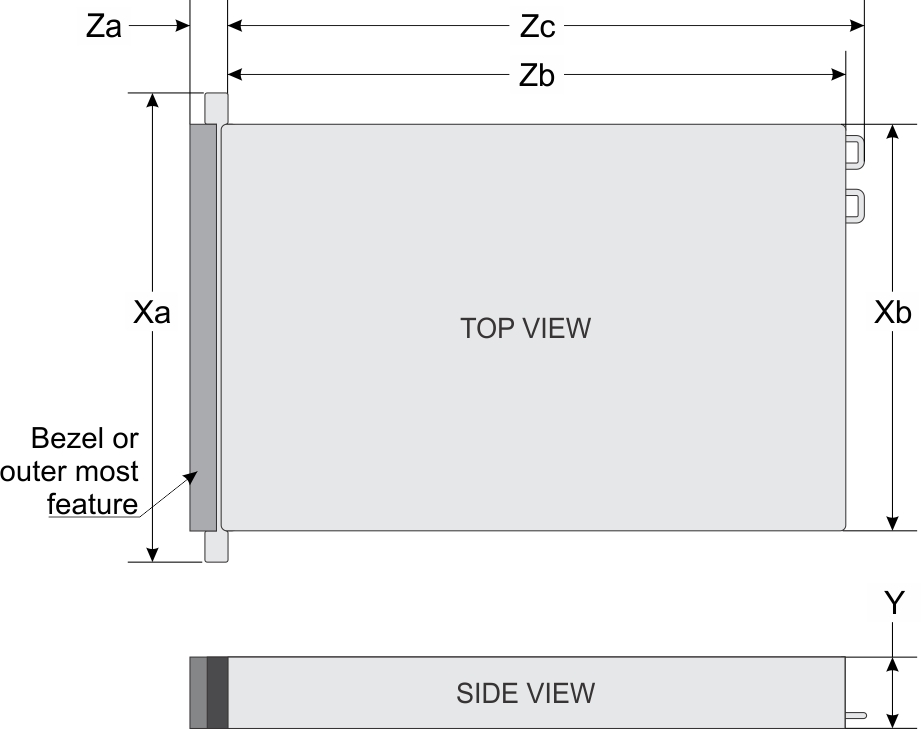
| System | Xa | Xb | Y | Za | Zb | Zc | ||
|---|---|---|---|---|---|---|---|---|
| Upper | Bottom | (with bezel) | (without bezel) | |||||
PowerEdge | 482.0 mm | 441.16 mm | 422.5 mm | 174.3 mm | 35.84 mm | 23.9 mm | 812 mm | 842 mm |
Chassis weight
| System | Maximum weight (with all drives) |
|---|---|
| PowerEdge R940xa (2.5 x 32 + X16 PCIe Riser 1/X16 PCIe Riser 2 riser with 4 DW GPU + 2 full height, half length PCIE cards) | 56.0 Kg (111.75 lb) |
Processor specifications
The PowerEdge R940xa system supports two or four Intel Xeon Processor Scalable Family (Skylake-EP) Gold and Platinum processors.
Supported operating systems
The supports the following operating systems:
RedHat Enterprise Linux
Novell SuSE Linux Enterprise Server
Microsoft Windows Server
Ubuntu
VMWare ESXi
Citrix Hypervisor
PSU specifications
The PowerEdge R940xa system supports up to four AC or DC power supply units (PSUs).
| PSU | Class | Heat dissipation (maximum) | Frequency | Voltage | High line 200v240 V | Low line 100– 140 V | DC | Current |
|---|---|---|---|---|---|---|---|---|
| 750 W Mixed Mode HVDC (for China only) | Platinum | 2891 BTU/hr | 50/60 Hz | 100–240 V AC, autoranging | 750 W | 750 W | N/A | 10 A–5 A |
| N/A | 2891 BTU/hr | N/A | 240 V DC, autoranging | N/A | N/A | 750 W | 4.5 A | |
| 750 W Mixed Mode AC | Platinum | 2891 BTU/hr | 50/60 Hz | 100–240 V AC | 750 W | 750 W | N/A | 10 A-5 A |
| 750 W Mixed Mode DC (for China only) | N/A | 2891 BTU/hr | 50/60 Hz | 240 V DC | 750 W | N/A | 750 W | 5 A |
| 1100 W AC | Platinum | 4100 BTU/hr | 50/60 Hz | 100–240 V AC, autoranging | 1100 W | 1050 W | N/A | 12 A–6.5 A |
| 1100 W DC | N/A | 4416 BTU/hr | N/A | –(48–60) V DC, autoranging | N/A | N/A | 1100 W | 32 A |
| 1100 W Mixed Mode HVDC (for China and Japan only) | Platinum | 4100 BTU/hr | 50/60 Hz | 100–240 V AC, autoranging | 1100 W | 1050 W | N/A | 12 A–6.5 A |
| N/A | 4100 BTU/hr | N/A | 200–380 V DC, autoranging | N/A | N/A | 1100 W | 6.4 A–3.2 A | |
| 1600 W HLAC | Titanium | 5840 BTU/hr | 50/60 Hz | 200–240 V AC | 1600 W | NA | NA | 10 A |
| 1600 W AC | Platinum | 6000 BTU/hr | 50/60 Hz | 100–240 V AC, autoranging | 1600 W | 800 W | N/A | 10 A |
| 2000 W AC | Platinum | 7500 BTU/hr | 50/60 Hz | 100–240 V AC, autoranging | 2000 W | 1000 W | N/A | 11.5 A |
| 2400 W AC | Platinum | 9000 BTU/hr | 50/60 Hz | 100–240 V AC, autoranging | 2400 W | 1400 W | N/A | 16 A |
| 2600 W HLAC | Titanium | 9500 BTU/hr | 50/60 Hz | 200–240 V AC | 2600 W | NA | NA | 15 A |
System battery specifications
The PowerEdge R940xa system supports CR 2032 3.0-V lithium coin cell system battery.
PCIe riser and slots
The PowerEdge R940xa system supports up to twelve PCI express (PCIe) generation 3 expansion cards that can be installed on the system board and expansion card risers. The following table provides detailed information about the expansion card riser specifications:
| Number of processors | NVMe | GPU | Riser size | Slot size | Slot quantity | Available slots | Height | Length |
|---|---|---|---|---|---|---|---|---|
| 4 | NA | GPU Ready/Double wide accelerators capable | X16 PCIe Riser 1 | X 16 | 2 | 2,4 | FH | FL |
| X 8 | 1 | 5 | FH | HL | ||||
| X16 PCIe Riser 2 | X 16 | 2 | 9,11 | FH | FL | |||
| X 8 | 1 | 12 | FH | HL | ||||
| NA | Non-GPU/Single wide FPGA | X8 PCIe Riser 1 | X 8 | 5 | 1,2,3,4,5 | FH | HL | |
| X8 PCIe Riser 2 | X 8 | 5 | 8,9,10,11,12 | FH | HL | |||
| Front NVMe | GPU Ready/Double wide accelerators capable | X16 PCIe Riser 1 | X 16 | 2 | 2,4 | FH | FL | |
| X16 PCIe Riser 2 | X 16 | 2 | 9,11 | FH | FL | |||
| Front NVMe | Non-GPU/Single wide FPGA | X8 PCIe Riser 1 | X 8 | 4 | 1,2,3,4 | FH | HL | |
| X8 PCIe Riser 2 | X 8 | 4 | 8,9,10,11 | FH | HL | |||
| 2 | NA | GPU Ready/Double wide accelerators capable | X16 PCIe Riser 1 | X 16 | 1 | 4 | FH | FL |
| X16 PCIe Riser 2 | X 16 | 1 | 11 | FH | FL | |||
| NA | Non-GPU/Single wide FPGA | X8 PCIe Riser 1 | X 8 | 2 | 3,4 | FH | HL | |
| X8 PCIe Riser 2 | X 8 | 2 | 10,11 | FH | HL |
Memory specifications
| Memory module sockets | DIMM type | DIMM rank | DIMM capacity | Dual processors | Quad processors | ||
|---|---|---|---|---|---|---|---|
| Minimum RAM | Maximum RAM | Minimum RAM | Maximum RAM | ||||
| 48 288-pins | LRDIMM | Octal rank | 256 GB | 512 GB | 6144 GB | 1024 GB | 12.288 TB |
| LRDIMM | Octal rank | 128 GB | 256 GB | 3072 GB | 512 GB | 6144 GB | |
| LRDIMM | Quad rank | 64 GB | 128 GB | 1536 GB | 256 GB | 3072 GB | |
| RDIMM | Dual rank | 64 GB | 128 GB | 1536 GB | 256 GB | 3072 GB | |
| RDIMM | Dual rank | 32 GB | 64 GB | 768 GB | 128 GB | 1536 GB | |
| RDIMM | Dual rank | 16 GB | 32 GB | 384 GB | 64 GB | 768 GB | |
| RDIMM | Single rank | 8 GB | 16 GB | 192 GB | 32 GB | 384 GB | |
| NVDIMM-N | Single rank | 16 GB | RDIMM: 192 GB | RDIMM: 384 GB | RDIMM: 384 GB | RDIMM: 1152 GB | |
| NVDIMM-N: 16 GB | NVDIMM-N: 192 GB | NVDIMM-N: 16 GB | NVDIMM-N: 192 GB | ||||
| PMem | N/A | 128 GB | RDIMM: 192 GB | LRDIMM: 1536 GB | RDIMM: 384 GB | LRDIMM: 3072 GB | |
| PMem: 1536 GB | PMem: 1536 GB | PMem: 248 GB | PMem: 3072 GB | ||||
| N/A | 256 GB | RDIMM: 384 GB | LRDIMM: 1536 GB | RDIMM: 384 GB | LRDIMM: 3072 GB | ||
| PMem: 2048 GB | PMem: 3072 GB | PMem: 4096 GB | PMem: 6144 GB | ||||
| N/A | 512 GB | RDIMM: 384 GB | LRDIMM: 1536 GB | RDIMM: 768 GB | LRDIMM: 3072 GB | ||
| PMem: 4096 GB | PMem: 6144 GB | PMem: 8192 GB | PMem: 12,288 GB | ||||
| Processor configuration | Processor 1 | Processor 2 | Processor 3 | Processor 4 |
|---|---|---|---|---|
| Dual processor | Required | Required | Not required | Not required |
| Quad processor | Required | Required | Required | Required |
PMem and 256GB LRDIMM Thermal Restrictions
| PMem Support | V2 Air-shroud | V1 Air-shroud |
| 8x 2.5-inch SAS/SATA |
30C ambient temperature support, 25C ambient temperature with 256GB LRDIMMs |
25C ambient temperature support, not supported with 256GB LRDIMM |
| 24x 2.5-inch SAS/SATA |
30C ambient temperature support, not supported with 256GB LRDIMM |
25C ambient temperature support, not supported with 256GB LRDIMM |
| 32x 2.5-inch SAS/SATA or mixed NVMe |
30C ambient temperature support, not supported with 256GB LRDIMM |
25C ambient temperature support, not supported with 256GB LRDIMM |
Storage controller specifications
- Internal storage controller cards: PowerEdge RAID Controller (PERC) H330, H350, PERC H730P, H830, H740P, H750, H840, HBA330, HBA350i, S140, and Boot Optimized Server Storage—BOSS-S1.
- External storage controller cards: 12 Gbps SAS HBA, including HBA355e.
Storage
The Dell EMC PowerEdge R940xa provide scalable storage that allows you to adapt to your workload and operational demands. The Dell EMC PowerEdge R940xa offers storage expansion with the middle hard drive tray and rear hard drive cage. The hard drive bay supports up to 32 2.5-inch hard drives or SSDs.
Drive
The PowerEdge R940xa system supports SAS, SATA, Nearline SAS hard drives/SSDs, or NVMe drives.
- 8 drives system - Up to eight 2.5-inch (SAS, SATA, or Nearline SAS) front accessible drives in slots 0 through 7.
- 32 drives system - Up to 24 2.5-inch (SAS, SATA, or Nearline SAS) including 4 NVMe front accessible drives (slots 20 to 23) in slots 0 to 23 of upper drives bay, and up to eight 2.5-inch (SAS, SATA, or Nearline SAS) front accessible drives in slots 24 to 31 of lower drives bay.
Internal storage configuration matrix
| HDD/SDD (not BOSS) | NVMe Enabled/Universal Slot | Internal Storage (Front) | Internal Storage (Rear) | PERC cards | Storage Controller(s) | Controller |
|---|---|---|---|---|---|---|
| 8 | 0/0 | 8 x 2.5 inch SATA (passive) | N/A | 1 | SATA S140 | N/A |
| 8 | 0/0 | 8 x 2.5 inch SAS/SATA (passive) | N/A | 1 | PERC H330, H350 | Adapter |
| 8 | 0/0 | 8 x 2.5 inch SAS/SATA (passive) | N/A | 1 | PERC H730P, H750 | Adapter |
| 8 | 0/0 | 8 x 2.5 inch SAS/SATA (passive) | N/A | 1 | PERC H740P, H750 | Adapter |
| 8 | 0/0 | 8 x 2.5 inch SAS/SATA (passive) | N/A | 1 | HBA330, HBA350 | Adapter |
| 32 | 0/0 | 24 x 2.5 inch SAS/SATA /NVMe (expander)
8 x 2.5 inch SAS/SATA (passive) |
N/A | 2 | PERC H740P, H750 | Adapter |
| 32 | 0/0 | 24 x 2.5 inch SAS/SATA /NVMe (expander)
8 x 2.5 inch SAS/SATA (passive) |
N/A | 2 | PERC H730P, H750 | Adapter |
| 32 | 0/0 | 24 x 2.5 inch SAS/SATA /NVMe (expander)
8 x 2.5 inch SAS/SATA (passive) |
N/A | 2 | PERC H330, H350 | Adapter |
| 32 | 0/0 | 24 x 2.5 inch SAS/SATA /NVMe (expander)
8 x 2.5 inch SAS/SATA (passive) |
N/A | 2 | HBA330, HBA350 | Adapter |
| 32 | 4/4 | 24 x 2.5 inch SAS/SATA /NVMe (expander)
8 x 2.5 inch SAS/SATA (passive) |
N/A | 2 | PERC H730P, H750
S140 (NVMe enablement) |
Adapter |
| 32 | 4/4 | 24 x 2.5 inch SAS/SATA /NVMe (expander)
8 x 2.5 inch SAS/SATA (passive) |
N/A | 2 | PERC H740P, H750
S140 (NVMe enablement) |
Adapter |
| 32 | 4/4 | 24 x 2.5 inch SAS/SATA /NVMe (expander)
8 x 2.5 inch SAS/SATA (passive) |
N/A | 2 | PERC H330, H350
S140 (NVMe enablement) |
Adapter |
| 32 | 4/4 | 24 x 2.5 inch SAS/SATA /NVMe (expander)
8 x 2.5 inch SAS/SATA (passive) |
N/A | 2 | HBA330, HBA350
S140 (NVMe enablement) |
Adapter |
Boot Optimized Storage Subsystem
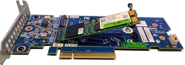
The Boot Optimized Storage Subsystem (BOSS) is offered as a means of booting PowerEdge systems to a full operating system mode when:
- Target operating system is a full operating system and not hypervisor that may be supported best by IDSDM
- You do not want to trade off standard hot plug drive slots for operating system install
The RAID controller on the BOSS card has limited set of features. This RAID controller presents the M.2 SATA SSDs as either a non-RAID volume or as a single RAID volume.
| Function or feature | Supported |
|---|---|
| Stripe size supported | 64 K |
| Configuration (HII) | Yes |
| Full initialization | No |
| Fast initialization | Yes
NOTE By default, fast initialization is performed when you create a virtual drive.
|
| Background initialization | No |
| RAID 0 | No |
| RAID 1 | Yes |
| Single non-RAID | Yes |
| Dual non-RAID | Yes |
| Degraded RAID1 and non-RAID | No |
| Foreign import | Yes |
| Consistency check | No |
| Patrol read | No |
| Load balance | N/A |
| Rebuild | Yes
NOTE You must manually start the rebuild process using HII or using the Marvell CLI.
|
| Auto-rebuild | Yes
NOTE Auto-rebuild is performed when the system is powered on only if there is a surviving native virtual drive and another hard drive is present.
|
| Hot spare | No |
| Change rebuild priority/rate. | No |
| Virtual disks write back/read ahead cache. | No
NOTE BOSS controller does not support controller cache.
|
| Battery support | N/A
NOTE BOSS controller does not support a battery.
|
| Non-RAID disk cache policy | Yes
NOTE Operating system controlled/Device defaults.
|
| SMART Info | Yes
NOTE Use the Marvell CLI to retrieve the SMART information from the drives.
|
| Physical disk hot swap | No |
| Virtual disk expansion | No |
| Virtual disk slicing | No |
| Virtual disk migration | Yes
NOTE On new controller, virtual disk must be Imported from HII before presented to operating system.
|
| Split mirror | No
NOTE System that is required to shutdown and migrate one hard drive to another system and continue rebuild.
|
| Non-RAID migration | Yes |
| BIOS configuration utility (Ctrl-M) | No |
| Add on driver for data path (operating system device driver). | No
NOTE Console Windows driver or Linux library is required for management purposes only.
|
| 4K native drive support | No |
| TRIM and UNMAP virtual disk | No |
| TRIM and UNMAP Non-RAID hard drive | Yes |
| Self-encrypting drives(SED) support | No |
| Cryptographic erase (sanitize). | Yes
NOTE If drive supports SANITIZE Crypto Erase. No other encryption support from controller or drive.
|
Optical drives
External storage
| Device Type | Description |
|---|---|
| External Tape | Supports connection to external USB tape products |
| NAS/IDM appliance software | Supports NAS software stack |
| JBOD | Supports connection to 12Gb MD-series JBODs |
Optical drives
The PowerEdge R940xa supports one of the following internal optical drive options:
- DVD-ROM
- DVD+RW
Tape drives
The PowerEdge R940xa does not support internal tape drives. However, external tape drives are supported. The supported external tape drives are as mentioned below:
- External RD1000 USB
- External LTO-5, LTO-6,LTO-7 and 6 Gb SAS tape drives
- 114X rack mount chassis with LTO-5, LTO-6, and LTO-7 6 Gb SAS tape drives
- TL1000 with LTO-5, LTO-6, and LTO-7 6 Gb SAS tape drives
- TL2000 with LTO-5, LTO-6, and LTO-7 6 Gb SAS tape drives
- TL2000 with LTO-5, LTO-6, and LTO-7 8Gb FC tape drives
- TL4000 with LTO-5, LTO-6, and LTO-7 6 Gb SAS tape drives
- TL4000 with LTO-5, LTO-6, and LTO-7 8Gb FC tape drives
- ML6000 with LTO-5, LTO-6, 6 Gb SAS tape drives
- ML6000 with LTO-5, LTO-6, LTO-7 8Gb FC tape drives
USB ports
- Two USB 2.0-compliant ports on the front of the system
- One internal USB 3.0-compliant port
- One optional USB 3.0-compliant port on the front
of the systemNOTE The USB 3.0 port is supported in the 8x2.5-inch configuration only.
- One micro USB 2.0-compliant port in the front of the
system for iDRAC DirectNOTE The micro USB 2.0 compliant port on the front of the system can only be used as an iDRAC Direct or a management port.
- Two USB 3.0-compliant ports on the back of the system
NIC ports
- Four RJ-45 ports that support 10, 100 and 1000 Mbps
- Four RJ-45 ports that support 100 M, 1 G and 10 Gbps
- Four RJ-45 ports, where two ports support maximum of 10 G and the other two ports maximum of 1 G
- Two RJ-45 ports that support up to 1 Gbps and 2 SFP+ ports that support up to 10 Gbps
- Four SFP+ ports that support up to 10 Gbps
- Two SFP28 ports that support up to 25 Gbps
VGA ports
The Video Graphic Array (VGA) port enables you to connect the system to a VGA display. The PowerEdge R940xa system supports two 15-pin VGA ports on the front and back panels.
Serial connector
The PowerEdge R940xa system supports one serial connector on the back panel, which is a 9-pin connector, Data Terminal Equipment (DTE), 16550-compliant.
IDSDM or vFlash module
- vFlash or
- vFlash and IDSDM
Video specifications
The PowerEdge R940xa system supports integrated Matrox G200eW3 graphics controller with 16 MB of video frame buffer.
| Resolution | Refresh Rate | Color depth (bits) | Horizontal Freq. | Pixel Clock | Rear Panel | Front Panel | DVO DisplayPort |
|---|---|---|---|---|---|---|---|
| 1024 x 768 | 60 Hz | 8, 16, 32 | 48.4 kHz | 65.0 MHz | Yes | Yes | Yes* |
| 1280 x 800 | 60 Hz | 8, 16, 32 | 49.7 kHz | 83.5 MHz | Yes | Yes | Yes* |
| 1280 x 1024 | 60 Hz | 8, 16, 32 | 64.0 kHz | 108.0 MHz | Yes | TBD | Yes* |
| 1360 x 768 | 60 Hz | 8, 16, 32 | 47.71 kHz | 85.5 MHz | Yes | Yes | Yes* |
| 1440 x 900 | 60 Hz | 8, 16, 32 | 55.9 kHz | 106.5 MHz | Yes | TBD | Yes* |
| 1600 x 900 | 60 Hz (RB) | 8, 16, 32 | 55.54 kHz | 97.75 MHz | Yes | Yes | Yes* |
| 1600 x 1200 | 60 Hz | 8, 16, 32 | 75.0 kHz | 162.0 MHz | TBD | TBD | Yes* |
| 1680 x 1050 | 60 Hz (RB) | 8, 16, 32 | 64.7 kHz | 119.0 MHz | Yes | TBD | Yes* |
| 1920 x 1080 | 60 Hz | 8, 16, 32 | 67.158 kHz | 173.0 MHz | TBD | No | No |
| 1920 x 1200 | 60 Hz | 8, 16, 32 | 74.556 kHz | 193.25 MHz | TBD | No | No |
Environmental specifications
| Temperature | Specifications |
|---|---|
| Storage | –40°C to 65°C (–40°F to 149°F) |
| Continuous operation (for altitude less than 950 m or 3117 ft) | 10°C to 35°C (50°F to 95°F) with no direct sunlight on the equipment. |
| Maximum temperature gradient (operating and storage) | 20°C/h (68°F/h) |
| Relative humidity | Specifications |
|---|---|
| Storage | 5% to 95% RH with 33°C (91°F) maximum dew point. Atmosphere must be non-condensing at all times. |
| Operating | 10% to 80% relative humidity with 29°C (84.2°F) maximum dew point. |
| Maximum vibration | Specifications |
|---|---|
| Operating | 0.26 Grms at 5 Hz to 350 Hz (all three axes). |
| Storage | 1.88 Grms at 10 Hz to 500 Hz for 15 min (all six sides tested). |
| Maximum shock | Specifications |
|---|---|
| Operating | Six consecutively executed shock pulses in the positive and negative x, y, and z axes of 6 G for up to 11 ms. |
| Storage | Six consecutively executed shock pulses in the positive and negative x, y, and z axes (one pulse on each side of the system) of 71 G for up to 2 ms. |
| Maximum altitude | Specifications |
|---|---|
| Operating | 3048 m (10,000 ft) |
| Storage | 12,000 m (39,370 ft) |
| Operating temperature de-rating | Specifications |
|---|---|
| Up to 35°C (95°F) | Maximum temperature is reduced by 1°C/300 m (1°F/547 ft) above 950 m (3,117 ft). |
| 35°C to 40°C (95°F to 104°F) | Maximum temperature is reduced by 1°C/175 m (1°F/319 ft) above 950 m (3,117 ft). |
| 40°C to 45°C (104°F to 113°F) | Maximum temperature is reduced by 1°C/125 m (1°F/228 ft) above 950 m (3,117 ft). |
Standard operating temperature
| Standard operating temperature | Specifications |
|---|---|
| Continuous operation (for altitude less than 950 m or 3117 ft) | 10°C to 35°C (50°F to 95°F) with no direct sunlight on the equipment. |
Thermal and acoustics
The system's thermal management delivers high performance through optimized cooling of components at the lowest fan speeds across a wide range of ambient temperatures from 10°C to 35°C (50°F to 95°F) and to extended ambient temperature ranges. These optimizations result in lower fan power consumption which translate to lower system power and data center power consumption.
Thermal design
The thermal design of the system reflects the following:
- Optimized thermal design: The system layout is architected for optimum thermal design. System component placement and layout are designed to provide maximum airflow coverage to critical components with minimal expense of fan power.
- Comprehensive thermal management: The thermal control system regulates the system fan speeds based on feedback from system component temperature sensors, as well as for system inventory and subsystem power draw. Temperature monitoring includes components such as processors, DIMMs, chipset, system inlet air ambient, hard disk drives, NDC, and GPU.
- Open and closed loop fan speed control: Open loop fan control uses system configuration to determine fan speed based on system inlet air temperature. Closed loop thermal control uses temperature feedback to dynamically adjust fan speeds based on system activity and cooling requirements.
- User-configurable settings: With the understanding and realization that every customer has a unique set of circumstances or expectations from the system, in this generation of servers, we have introduced limited user-configurable settings in the iDRAC9 BIOS setup screen. For more information, see the Dell EMC PowerEdge system Installation and Service Manual on Dell.com/Support/Manuals and “Advanced Thermal Control: Optimizing across Environments and Power Goals” on Dell.com.
Cooling redundancy: The system allows N+1 fan redundancy, allowing continuous operation with one fan failure in the system.
- Environmental Specifications: The optimized thermal management makes the R940xa reliable under a wide range of operating environments.
Expanded operating temperature restrictions
- The operating temperature is for a maximum altitude of 950 m for fresh air cooling
- No cold start-ups below 5°C due to hard drive constraints
- Apache Pass DIMM, NVDIMM, PCIeSSD and NVME are not supported
- GPGPU configuration are not supported
- LRDIMM > 32 GB are not supported in x4 socket configurations
- DCPMMs are not supported.
- Redundant power supply units are required
- Non Dell qualified peripheral cards and /or peripheral cards greater than 25 W are not supported
- Intel FPGA is not supported
- Mellanox CX5 is not supported
Fresh air restrictions
Following table lists the configuration required for efficient cooling.
| Processors | Number of Processor/GPUs | Number of drives | Ambient temperature | Fresh air support | Fan type | Processors | Shroud | |
|---|---|---|---|---|---|---|---|---|
| Up to 304W processor (CPU 1/2) | Up to 304W processor (CPU 3/4) | |||||||
| All | GPU/2&4 CPU | 32x2.5-inch, w/ NVMe | 30 | No AEP | Six standard | 2U height HSK | 4U height HSK | Remove the air shroud A |
| (L-shape) | ||||||||
| All | No GPU /2&4 CPU | 32x2.5-inch, w/ NVMe | 35 | No AEP | Six standard | 2U height HSK | 4U height HSK | Install the air shroud A |
| (L-shape) | ||||||||
| 205W / 200W / 165W_12C / 150W_8C CPU | No GPU /4 CPU | 32x2.5-inch, w/o NVMe | 35 | No AEP | Six standard | 2U height HSK | 4U height HSK | Install the air shroud A |
| (L-shape) | ||||||||
| Processor TDP <= 165W | No GPU /4 CPU | 32x2.5-inch, w/o NVMe | C40E45 | Non-support FA with GPU, AEP, NVDIMM, PCIeSSD, NVMe and INTEL FPGALRDIMM > 32G | Six standard | 2U height HSK | 4U height HSK | Install the air shroud A |
| (L-shape) | ||||||||
| All | No GPU /2 CPU | 32x2.5-inch, w/o NVMe | C40E45 | Non-support FA with GPU, AEP, NVDIMM, PCIeSSD, NVMe and INTEL FPGA | Six standard | 2U height HSK | 4U height HSK | Install the air shroud A |
| (L-shape) | ||||||||
| All | GPU/2&4 CPU | 8x2.5-inch | 30 | No AEP | Six standard | 2U height HSK | 4U height HSK | Remove the air shroud A |
| (L-shape) | ||||||||
| All | No GPU /2&4 CPU | 8x2.5-inch | C40E45 | Non-support FA with GPU, AEP, NVDIMM, PCIeSSD, NVMe and INTEL FPGALRDIMM > 32G | Six standard | 2U height HSK | 4U height HSK | Install the air shroud A |
| (L-shape) | ||||||||
Thermal restrictions
Following table lists the configuration required for efficient cooling.
| Number of hard drives | Risers | Number of processors | Number of GPUs | Heat sink | Fan type | Shroud | DIMM blank | Processor/DIMM blank | Fan blank | |
|---|---|---|---|---|---|---|---|---|---|---|
| Up to 205W processor (CPU 1/2) | Up to 205W processor (CPU 3/4) | |||||||||
| 24 x 2.5 inch SAS/SATA + | 12 PCIe (X8 PCIe Riser 1/X8 PCIe Riser 2) | 2 | N/A | 2U height HSK | N/A | Six standard | Standard | Yes (max 22x) | N/A | N/A |
| 8 x 2.5 inch SAS/SATA | ||||||||||
| 24 x 2.5 inch SAS/SATA + | 12 PCIe (X8 PCIe Riser 1/X8 PCIe Riser 2) | 4 | N/A | 2U height HSK | 4U height HSK | Six standard | Standard | Yes (max 44x) | N/A | N/A |
| 8 x 2.5 inch SAS/SATA | (L-shape) | |||||||||
| 24 x 2.5 inch SAS/SATA + | 8 PCIe (X16 PCIe Riser 1/X16 PCIe Riser 2) | 2 | 2 | 2U height HSK | N/A | Six standard | Remove the GPU shroud | Yes (max 22x) | N/A | N/A |
| 8 x 2.5 inch SAS/SATA | ||||||||||
| 24 x 2.5 inch SAS/SATA + | 8 PCIe (X16 PCIe Riser 1/X16 PCIe Riser 2) | 4 | 2 | 2U height HSK | 4U height HSK | Six standard | Remove the GPU shroud | Yes (max 44x) | N/A | N/A |
| 8 x 2.5 inch SAS/SATA | (L-shape) | |||||||||
| 24 x 2.5 inch SAS/SATA + | 8 PCIe (X16 PCIe Riser 1/X16 PCIe Riser 2) | 4 | 4 | 2U height HSK | 4U height HSK | Six standard | Remove the GPU shroud | Yes (max 44x) | N/A | N/A |
| 8 x 2.5 inch SAS/SATA | (L-shape) | |||||||||
| 8 x 2.5 inch SAS/SATA | 12 PCIe (X8 PCIe Riser 1/X8 PCIe Riser 2) | 2 | N/A | 2U height HSK | N/A | Six standard | Standard | Yes (max 22x) | N/A | N/A |
| 8 x 2.5 inch SAS/SATA | 12 PCIe (X8 PCIe Riser 1/X8 PCIe Riser 2) | 4 | N/A | 2U height HSK | 4U height HSK | Six standard | Standard | Yes (max 44x) | N/A | N/A |
| (L-shape) | ||||||||||
| 8 x 2.5 inch SAS/SATA | 8 PCIe (X16 PCIe Riser 1/X16 PCIe Riser 2) | 2 | 2 | 2U height HSK | N/A | Six standard | Remove the GPU shroud | Yes (max 22x) | N/A | N/A |
| 8 x 2.5 inch SAS/SATA | 8 PCIe (X16 PCIe Riser 1/X16 PCIe Riser 2) | 4 | 2 | 2U height HSK | 4U height HSK | Six standard | Remove the GPU shroud | Yes (max 44x) | N/A | N/A |
| (L-shape) | ||||||||||
| 8 x 2.5 inch SAS/SATA | 8 PCIe (X16 PCIe Riser 1/X16 PCIe Riser 2) | 4 | 4 | 2U height HSK | 4U height HSK | Six standard | Remove the GPU shroud | Yes (max 44x) | N/A | N/A |
| (L-shape) | ||||||||||
Ambient temperature limitations
The following table lists configurations that require ambient temperature less than 30°C:
| System | Backplane | CPU Thermal Design Power (TDP) | CPU heat sink | Fan type | GPU | Ambient restriction |
|---|---|---|---|---|---|---|
| PowerEdge R940xa | 24 x 2.5 inch SAS/ SATA + 8 x 2.5 inch SAS/SATA | Up to 205 W | 2U height HSK + 4U height HSK | Standard fan | ≥1 double-width/ single-width | 30°C |
| 8 x 2.5 inch SAS/SATA | Up to 205 W | 2U height HSK + 4U height HSK | Standard fan | ≥1 double-width/ single-width | 30°C |
Particulate and gaseous contamination specifications
| Particulate contamination | Specifications |
|---|---|
| Air filtration | Data center air filtration as defined by ISO Class
8 per ISO 14644-1 with a 95% upper confidence limit. NOTE The ISO Class 8 condition
applies to data center environments only. This air filtration requirement
does not apply to IT equipment designed to be used outside a data
center, in environments such as an office or factory floor. NOTE Air entering the data center must have MERV11 or MERV13 filtration. |
| Conductive dust | Air must be free of conductive dust, zinc whiskers,
or other conductive particles. NOTE This condition applies
to data center and non-data center environments. |
| Corrosive dust |
NOTE This condition
applies to data center and non-data center environments. |
| Gaseous contamination | Specifications |
|---|---|
| Copper coupon corrosion rate | <300 Å/month per Class G1 as defined by ANSI/ISA71.04-2013. |
| Silver coupon corrosion rate | <200 Å/month as defined by ANSI/ISA71.04-2013. |