




























System dimensions
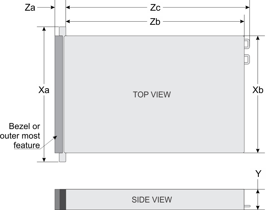
| System | Xa | Xb | Y | Za (with bezel) | Za (without bezel) | Zb | Zc |
|---|---|---|---|---|---|---|---|
| PowerEdge R940 | 482.0 mm (18.9 inches) | 434.0 mm (17.08 inches) | 130.3 mm (5.13 inches) | 35.0 mm (1.37 inches) | 22.0 mm (0.86 inches) | 726.2 mm (28.59 inches) | 777.046 mm (30.59 inches) |
System weight
| System | Maximum weight (with all hard drive/SSDs) |
|---|---|
| PowerEdge R940 | 49.9 kg (110.01 lb) |
Cooling fan specifications
Processor specifications
PSU specifications
- Two 2400 W, 2000 W, 1600 W, or 1100 W AC power supply units (PSUs)
- Two 1100 W DC PSUs
- Two 1100 W Mixed Mode HVDC PSUs
- NOTE: The PowerEdge R940 system supports hot swappable PSUs.
- CAUTION: If two PSUs are installed, both the PSUs must have the same type of label. For example, Extended Power Performance (EPP) label. Mixing PSUs from previous generations of PowerEdge servers is not supported, even if the PSUs have the same power rating. This results in a PSU mismatch condition or failure to turn the system on.
- NOTE: Titanium PSU is nominally rated for 200 V AC to 240 V AC input only.
- NOTE: When two identical PSUs are installed, power supply redundancy (1+1 – with redundancy or 2+0 – without redundancy) is configured in system BIOS. In redundant mode, power is supplied to the system equally from both PSUs when Hot Spare is disabled. When Hot Spare is enabled, one of the PSUs is put into the sleep mode when system utilization is low in order to maximize efficiency.
- NOTE: If two PSUs are used, they must be of the same maximum output power.
| PSU | Class | Heat dissipation (maximum) | Frequency | Voltage | Power rating | Current |
|---|---|---|---|---|---|---|
| 1100 W AC | Platinum | 4100 BTU/hr | 50/60 Hz | 100–120 V AC, autoranging | derated to 1050 W | 12 A–6.5 A |
| 200–240 V AC, autoranging | 1100 W | |||||
| 1100 W DC | N/A | 4416 BTU/hr | N/A | –(48–60) V DC, autoranging | 1100 W | 32 A |
| 1100 W Mixed Mode HVDC (for China and Japan only) | Platinum | 4100 BTU/hr | 50/60 Hz | 100–120 V AC, autoranging | derated to 1050 W | 12 A–6.5 A |
| N/A | 4100 BTU/hr | N/A | 200–380 V DC, autoranging | 1100 W | 6.4 A–3.2 A | |
| 1600 W AC | Platinum | 6000 BTU/hr | 50/60 Hz | 100–120 V AC, autoranging | derated to 800 W | 10 A |
| 200–240 V AC, autoranging | 1600 W | |||||
| 2000 W AC | Platinum | 7500 BTU/hr | 50/60 Hz | 100–120 V AC, autoranging | derated to 1000 W | 11.5 A |
| 200–240 V AC, autoranging | 2000 W | |||||
| 2400 W AC | Platinum | 9000 BTU/hr | 50/60 Hz | 100-120 V AC, autoranging | derated to 1400 W | 16 A |
| 200–240 V AC, autoranging | 2400 W |
- NOTE: Heat dissipation is calculated using the PSU wattage rating.
- NOTE: This system is also designed to connect to the IT power systems with a phase to phase voltage not exceeding 240 V.
- NOTE: PSUs rated for 1600 W and higher require high-line voltage (200-240 V) to supply their rated capacity.
System battery specifications
Expansion bus specifications
| PCIe slot on the system board | Processor connection | PCIe slots on system board (Height) | PCIe slots on system board (length) | Link width | Slot width |
|---|---|---|---|---|---|
| Slot 1 | Processor 1 | full height | half length | x8 | x16 |
| Slot 2 | Processor 1 | full height | half length | x16 | x16 |
| Slot 3 | Processor 1 | full height | half length | x16 | x16 |
| Slot 4 | Processor 2 | full height | half length | x16 | x16 |
| Slot 5 | Processor 2 | full height | half length | x8 | x16 |
| Slot 6 | Processor 2 | full height | half length | x8 | x16 |
| Slot 7 | Processor 2 | full height | half length | x16 | x16 |
| Riser | PCIe slot on the expansion card riser | Processor connection | PCIe slots on riser (Height) | PCIe slots on riser (length) | Link width | Slot width |
|---|---|---|---|---|---|---|
| Riser 2 (IO_RISER2) | Slot 8 | Processor 3 | full height | 3/4 length | x16 | x16 |
| Slot 9 | Processor 3 | full height | half length | x16 | x16 | |
| Slot 10 | Processor 3 | full height | half length | x16 | x16 | |
| Riser 3 (IO_RISER3) | Slot 11 | Processor 4 | full height | 3/4 length | x16 | x16 |
| Slot 12 | Processor 4 | full height | half length | x16 | x16 | |
| Slot 13 | Processor 4 | full height | half length | x16 | x16 |
Memory specifications
| DIMM type | DIMM rank | DIMM capacity | Dual processors | Quad processors | ||
|---|---|---|---|---|---|---|
| Minimum RAM | Maximum RAM | Minimum RAM | Maximum RAM | |||
| LRDIMM | Octal Rank | 128 GB | 256 GB | 3,072 GB | 512 GB | 6,144 GB |
| LRDIMM | Quad Rank | 64 GB | 128 GB | 1,536 GB | 256 GB | 3,072 GB |
| RDIMM | Dual Rank | 32 GB | 64 GB | 768 GB | 128 GB | 1,536 GB |
| RDIMM | Dual Rank | 16 GB | 32 GB | 384 GB | 64 GB | 768 GB |
| RDIMM | Single Rank | 8 GB | 16 GB | 192 GB | 32 GB | 384 GB |
| NVDIMM-N | Single Rank | 16 GB | 16 GB | 192 GB | Supported on the system board only (No NVDIMM-N on PEM) | |
- NOTE: 8 GB RDIMM and NVDIMM-N must not be mixed.
- NOTE: NVDIMM-N memory modules must be installed only on the memory sockets available on the system board.
Storage controller specifications
- Internal controllers: S140 (NVMe drives only), and NVMe PCIe SSD adapter.
- Internal controllers: PowerEdge RAID Controller (PERC) H330, H730P, H740P Boot optimized storage subsystem.
- External HBAs (RAID): H840
- External HBAs (non-RAID): 12Gbps SAS HBA
Remote management port specifications
Hard drives
The PowerEdge R940 system supports SAS, SATA, Nearline SAS, NVMe hard drives or SSDs.
| Eight drives system | Up to eight 2.5-inch (SAS, SATA or Nearline SAS) front accessible drives in slots 0 through 7 |
| Twenty four drives system | Up to twenty four 2.5-inch (SAS, SATA or Nearline SAS) front accessible drives in slots 0 through 23 |
| Twenty four drives system | Up to twenty SAS + 4 NVMe SAS/SATA drives in slots 0 to 19 + slots 20 to 23 |
| Twenty four drives system | Up to sixteen SAS + 8 NVMe SAS/SATA drives in slots 0 to 15 + slots 16 to 23 |
USB ports
- Two USB 3.0-compliant ports on the front panel
- Two USB 3.0-compliant ports on the back panel
- One USB 3.0-compliant internal port
An optional USB memory key installed inside your system can be used as a boot device, security key, or mass storage device. To boot from the USB memory key, configure the USB memory key with a boot image and then specify the USB memory key in the boot sequence in System Setup.
NIC ports
- Four RJ-45 ports that support 10, 100, and 1000 Mbps
- Four RJ-45 ports that support 100 M, 1 G and 10 Gbps
- Four RJ-45 ports, where two ports support maximum of 10 G and the other two ports maximum of 1 G
- Two RJ-45 ports that support up to 1 Gbps and 2 SFP+ ports that support up to 10 Gbps
- Four SFP+ ports that support up to 10 Gbps
- Two SFP28 ports that support up to 25 Gbps
Serial port
Internal Dual SD Module or vFlash card
The PowerEdge R940 system supports Internal Dual SD module (IDSDM) and vFlash card. In 14th generation of PowerEdge servers, IDSDM and vFlash card are combined into a single card module, and are available in these configurations:
- vFlash or
- IDSDM or
- vFlash and IDSDM
The IDSDM/vFlash card sits in the back of the system, in a Dell-proprietary slot. IDSDM/vFlash card supports three micro SD cards (two cards for IDSDM and one card for vFlash). Micro SD cards capacity for IDSDM are 16/32/64 GB while for vFlash the microSD card capacity is 16 GB.
- NOTE: The write-protect switch is on the IDSDM or vFlash module.
VGA ports
Video specifications
| Resolution | Refresh rate (Hz) |
|---|---|
| 1024 x 768 | 60 |
| 1280 x 800 | 60 |
| 1280 x 1024 | 60 |
| 1360 x 768 | 60 |
| 1440 x 900 | 60 |
| 1600 x 900 | 60 (RB) |
| 1600 x 1200 | 60 |
| 1680 x 1050 | 60 (RB) |
| 1920 x 1080 | 60 |
| 1920 x 1200 | 60 |
Environmental specifications
- NOTE: For additional information about environmental certifications, please refer to the Product Environmental Datasheet located with the Manuals & Documents on Dell.com/poweredgemanuals .
| Temperature | Specifications |
|---|---|
| Storage | –40°C to 65°C (–40°F to 149°F) |
| Continuous operation (for altitude less than 950 m or 3117 ft) | 10°C to 35°C (50°F to 95°F) with no direct sunlight on the equipment. |
| Maximum temperature gradient (operating and storage) | 20°C/h (68°F/h) |
| Relative humidity | Specifications |
|---|---|
| Storage | 5% to 95% RH with 33°C (91°F) maximum dew point. Atmosphere must be non-condensing at all times. |
| Operating | 10% to 80% relative humidity with 26°C (78.8°F) maximum dew point. |
| Maximum vibration | Specifications |
|---|---|
| Operating | 0.26 G rms at 5 Hz to 350 Hz (all operation orientations). |
| Storage | 1.87 G rms at 10 Hz to 500 Hz for 15 min (all six sides tested). |
| Maximum shock | Specifications |
|---|---|
| Operating | Six consecutively executed shock pulses in the positive and negative x, y, and z axes of 6 G for up to 11 ms. |
| Storage | Six consecutively executed shock pulses in the positive and negative x, y, and z axes (one pulse on each side of the system) of 71 G for up to 2 ms. |
| Maximum altitude | Specifications |
|---|---|
| Operating |
3048 m ( 10,000 ft) |
| Storage | 12,000 m (39,370 ft) |
| Operating temperature de-rating | Specifications |
|---|---|
| Up to 35°C (95°F) | Maximum temperature is reduced by 1°C/300 m (1°F/547 ft) above 950 m (3,117 ft). |
| 35°C to 40°C (95°F to 104°F) | Maximum temperature is reduced by 1°C/175 m (1°F/319 ft) above 950 m (3,117 ft). |
| 40°C to 45°C (104°F to 113°F) | Maximum temperature is reduced by 1°C/125 m (1°F/228 ft) above 950 m (3,117 ft). |
Particulate and gaseous contamination specifications
| Particulate contamination | Specifications |
|---|---|
| Air filtration | Data center air filtration as defined by ISO Class
8 per ISO 14644-1 with a 95% upper confidence limit.
|
| Conductive dust | Air must be free of conductive dust, zinc whiskers,
or other conductive particles.
|
| Corrosive dust |
|
| Gaseous contamination | Specifications |
|---|---|
| Copper coupon corrosion rate | <300 Å/month per Class G1 as defined by ANSI/ISA71.04-1985. |
| Silver coupon corrosion rate | <200 Å/month as defined by AHSRAE TC9.9. |
- NOTE: Maximum corrosive contaminant levels measured at ≤50% relative humidity.
Standard operating temperature
| Standard operating temperature | Specifications |
|---|---|
| Continuous operation (for altitude less than 950 m or 3117 ft) | 10°C to 35°C (50°F to 95°F) with no direct sunlight on the equipment. |
| Humidity percentage range | 10% to 80% Relative Humidity with 26°C (78.8°F) maximum dew point. |
Expanded operating temperature
| Expanded operating temperature | Specifications |
|---|---|
| Continuous operation | 5°C to 40°C at 5% to 85% RH with 29°C dew point.
For temperatures between 35°C and 40°C, de-rate maximum allowable dry bulb temperature by 1°C per 175 m above 950 m (1°F per 319 ft). |
| Less than or equal to 1% of annual operating hours | –5°C to 45°C at 5% to 90% RH with 29°C dew point.
For temperatures between 40°C and 45°C, de-rate maximum allowable temperature by 1°C per 125 m above 950 m (1°F per 228 ft). |
- NOTE: When operating in the expanded temperature range, system performance may be impacted.
- NOTE: When operating in the expanded temperature range, ambient temperature warnings maybe reported on the LCD panel and in the System Event Log.
Expanded operating temperature restrictions
- Do not perform a cold startup below 5°C.
- The operating temperature specified is for a maximum altitude of 3050 m (10,000 ft).
- 150 W/8 core or higher wattage processor [Thermal Design Power (TDP)>165 W] is not supported.
- Redundant power supply unit is required.
- Non-Dell qualified peripheral cards and/or peripheral cards greater than 25 W are not supported.
- NVMe drives are not supported.
- NVDIMMs are not supported.
Thermal restrictions
Following table lists the configuration required for efficient cooling:
| Configuration | Number of processors | Heatsink | Processor blank | DIMM blanks | Fresh air | Fan |
|---|---|---|---|---|---|---|
| Eight 2.5 inch hard drive system | 2 | Two heat sinks for CPU < 165W | Not required | 12 | Yes | eight standard fans |
|
Two heat sinks for CPU ≥ 165 W |
No | |||||
| 4 | Four standard heat sinks for CPU < 165 W | Not required | 24 | Yes | eight standard fans | |
| Four heat sinks CPU ≥ 165 W | No | |||||
| Twenty four 2.5 inch hard drive system | 2 | Two standard heat sinks for CPU < 165W | Not required | 12 | Yes | eight standard fans |
| Two heat sinks for CPU ≥ 165 W | No | |||||
| 4 | Four standard heat sinks for CPU < 165 W | Not required | 24 | Yes | eight standard fans | |
| Four heat sinks for CPU ≥ 165 W | No |
| Configuration | Slot restriction | Ambient restriction |
|---|---|---|
| Eight 2.5-inch hard drive system | Slots 1, 5, and 6 do not support NIC cards | 35°C |
| Twenty four 2.5-inch hard drive system | Slots 1, 5, and 6 do not support NIC cards | 35°C |