





























Chassis dimensions
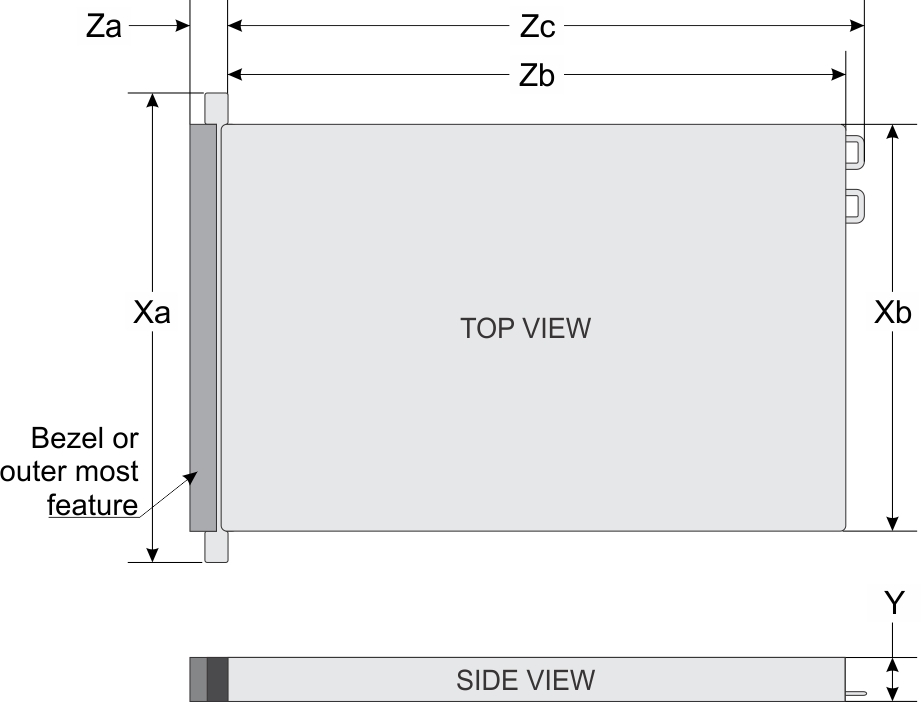
| Drives | Xa | Xb | Y | Za | Zb | Zc |
|---|---|---|---|---|---|---|
| 24 drives | 482.0 mm (18.97 inches) | 434.0 mm (17.08 inches) | 86.8 mm (3.41 inches) | 22.0 mm (0.86 inches)Without bezel35.84 mm (1.41 inches)With bezel | 675.04 mm (26.57 inches)Ear to L bracket housing650.24 mm (25.6 inches)Ear to PSU surface | 685.78 mm (26.99 inches)Ear to PSU handle without velcro strap |
| 12 drives | ||||||
| 16 drives | ||||||
| 8 drives | ||||||
| No backplane configuration |
System weight
| System configuration | Maximum weight (with all drives/SSDs/bezel) |
|---|---|
| 24 x 2.5-inch (16 SAS/SATA + 8 NVMe) | 23.84 kg (52.55 lb) |
| 16 x 2.5-inch | 21.94 kg (48.36 lb) |
| 12 x 3.5-inch | 28.76 kg (63.40 lb) |
| 8 x 3.5-inch | 24.80 kg (54.67 lb) |
| 8 x 2.5-inch | 20.44 kg (45.06 lb) |
| No backplane configuration | 18.54 kg (40.87 lb) |
Processor specifications
| Supported processor | Number of processors supported |
|---|---|
| 3rd Generation Intel Xeon Scalable processors with up to 32 cores | Up to two |
PSU specifications
The PowerEdge R750xs system supports up to two AC or DC power supply units (PSUs).
| PSU | Class | Heat dissipation (maximum) BTU/hr | Frequency Hz | Voltage | AC | DC | Current | |
|---|---|---|---|---|---|---|---|---|
| High line 200–240 V | Low line 100–120 V | |||||||
| 1400 W Mixed Mode | Platinum | 5406 | 50/60 | 100–240 V AC, autoranging | 1400 W | 1050 W | NA | 12 A–8 A |
| NA | 5406 | NA | 240 V DC, autoranging | NA | NA | 1400 W | 6.6 A | |
| 1100 W Mixed Mode | Titanium | 4299 | 50/60 | 100–240 V AC, autoranging | 1100 W | 1050 W | NA | 12 A–6.3 A |
| NA | 4299 | NA | 240 V DC, autoranging | NA | NA | 1100 W | 5.2 A | |
| 1100 W DC | NA | 4265 | NA | -48–(-60) V | NA | NA | 1100 W | 26.1 A |
| 800 W Mixed Mode | Platinum | 3000 | 50/60 | 100–240 V AC, autoranging | 800 W | 800 W | NA | 9.2 A-4.7 A |
| NA | 3000 | NA | 240 V DC, autoranging | NA | NA | 800 W | 3.8 A | |
| 600 W Mixed Mode | Platinum | 2250 | 50/60 | 100–240 V AC, autoranging | 600 W | 600 W | NA | 7.1 A-3.6 A |
| NA | 2250 | NA | 240 V DC, autoranging | NA | NA | 600 W | 2.9 A | |
Supported operating systems
The PowerEdge R750xs system supports the following operating systems:
- Canonical Ubuntu Server LTS
- Citrix Hypervisor
- Microsoft Windows Server with Hyper-V
- Red Hat Enterprise Linux
- SUSE Linux Enterprise Server
- VMware ESXi
For more information, go to www.dell.com/ossupport.
Cooling fan specifications
Cooling fan specifications
The PowerEdgeR750xs system supports up to sixStandard fans, High performance Silver Grade fans, or High performance Gold Grade fans .
| Fan type | Abbreviation | Also known as | Label color | Label image |
|---|---|---|---|---|
| Standard fan | STD | STD | No label | 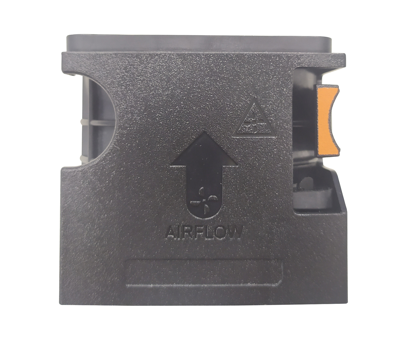 |
| High-performance fan (Silver grade) fan | HPR SLVR | HPR | Silver | NOTE New cooling fans come with the High-Performance Silver Grade label. While the older cooling fans have the High-Performance label.
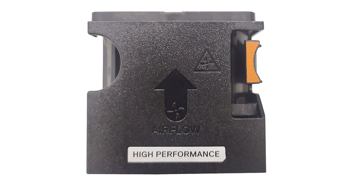 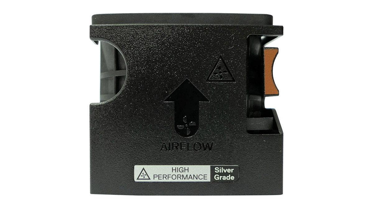 |
| High-performance fan (Gold grade) fan | HPR GOLD | VHPR - Very High Performance | Gold | NOTE New cooling fans come with the High-Performance Gold Grade label. While the older cooling fans have the High-Performance label.
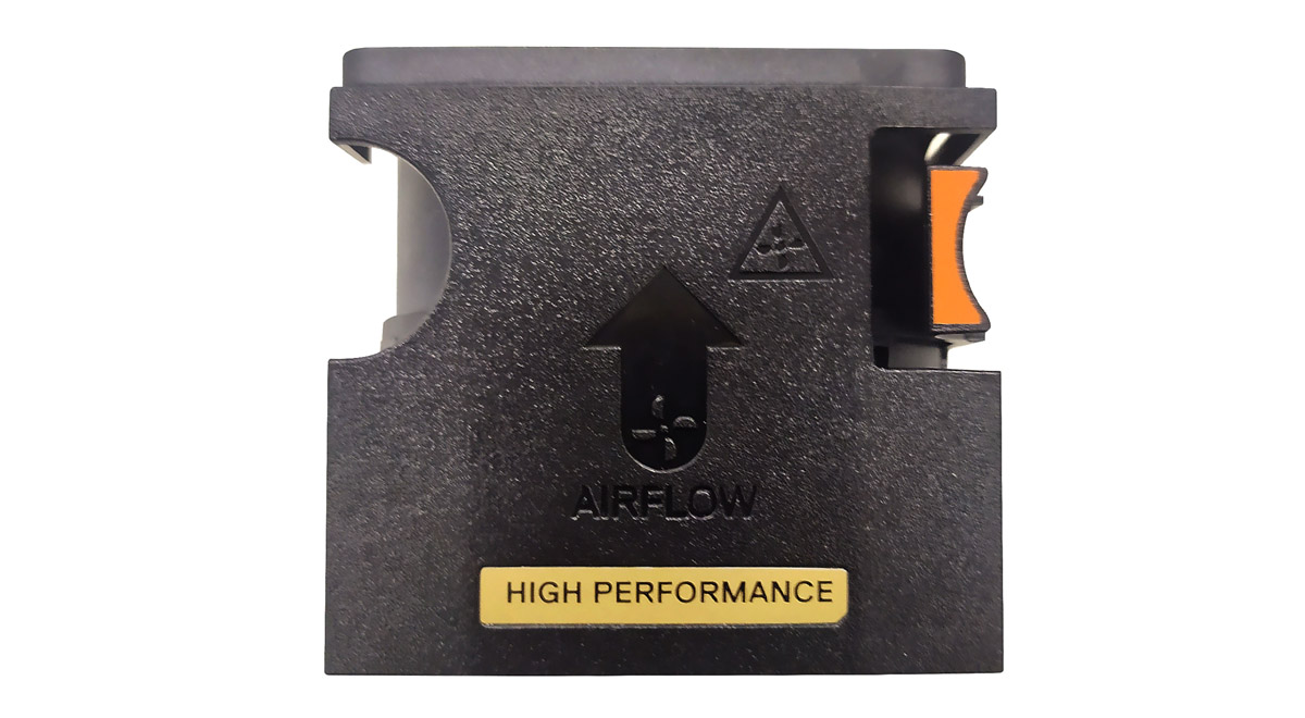 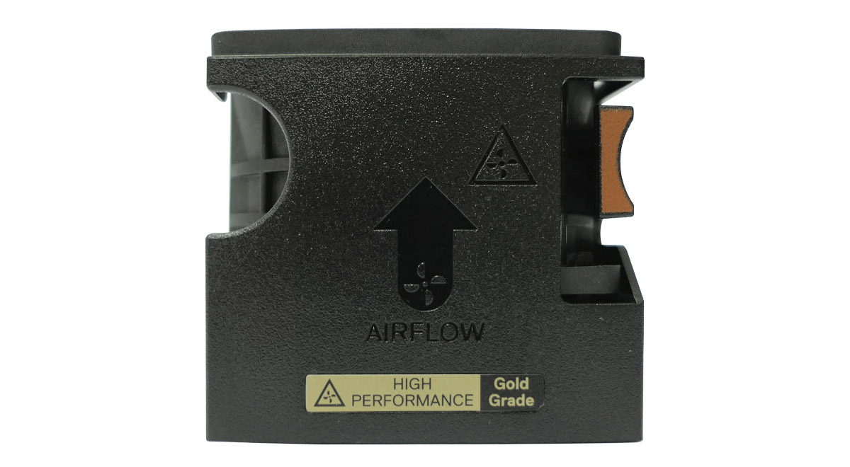 |
System battery specifications
The PowerEdge R750xs system supports CR 2032 3.0-V lithium coin cell system battery.
Expansion card riser specifications
| PCIe slot | Expansion card riser | Processor connection | Height | Length | Slot width |
|---|---|---|---|---|---|
| Slot 1 | N/A | Processor 1 | Low Profile | Half Length | x16 |
| Slot 2 | N/A | PCH | Low Profile | Half Length | x8 (x4-Link) |
| Slot 3 | Riser 1A | Processor 1 | Low Profile | Half Length | x16 |
| Slot 4 | Processor 2 | Low Profile | Half Length | x16 | |
| Slot 3 | Riser 1B (SNAPI) | Processor 1 and 2 | Low Profile | Half Length | x16 |
| Slot 4 | Processor 2 | Low Profile | Half Length | x16 (x8-Link) | |
| Slot 5 | N/A | Processor 2 | Low Profile | Half Length | x16 |
| Slot 6 | N/A | Processor 2 | Low Profile | Half Length | x16 |
Memory specifications
| DIMM type | DIMM rank | DIMM capacity | Single processor | Dual processors | ||
|---|---|---|---|---|---|---|
| Minimum DIMM capacity | Maximum DIMM capacity | Minimum DIMM capacity | Maximum DIMM capacity | |||
| RDIMM | Single rank | 8 GB | 8 GB | 64 GB | 16 GB | 128 GB |
| Dual rank | 16 GB | 16 GB | 128 GB | 32 GB | 256 GB | |
| 32 GB | 32 GB | 256 GB | 64 GB | 512 GB | ||
| 64 GB | 64 GB | 512 GB | 128 GB | 1 TB | ||
| Memory module sockets | Speed |
|---|---|
| 16, 288-pin | 3200 MT/s, 2933 MT/s, 2666 MT/s |
Storage controller specifications
| Internal controllers | External controllers |
|---|---|
|
|
Drives
- 24 x 2.5-inch (16 SAS/SATA + 8 NVMe) drives
- 16 x 2.5-inch SAS or SATA drives
- 12 x 3.5-inch SAS or SATA drives
- 8 x 2.5-inch SAS or SATA drives
- 8 x 2.5-inch NVMe drives
- 8 x 3.5-inch SAS or SATA drives
USB ports specifications
| Front | Rear | Internal (Optional) | |||
|---|---|---|---|---|---|
| USB port type | No. of ports | USB port type | No. of ports | USB port type | No. of ports |
| USB 2.0-compliant port | One | USB 2.0-compliant port | One | Internal USB 3.0-compliant port | One |
| Micro-USB 2.0 iDRAC Direct | One | USB 3.0-compliant port | One | ||
Serial connector specifications
The PowerEdge R750xs system supports one optional card type serial connector on rear of the system, which is a 9-pin connector, Data Terminal Equipment (DTE), 16550-compliant .
The process to install the optional serial connector card is similar to an expansion card filler bracket.
NIC port specifications
| Feature | Specifications |
|---|---|
| LOM | 1 GB x 2 |
| OCP card (OCP 3.0) | 1 GbE x 4, 10 GbE x 2, 25 GbE x 2, 25 GbE x 4, 50 GbE x 2, 100 GbE x 2 |
VGA ports specifications
The PowerEdge R750xs system supports two DB-15 VGA ports, one each on the front and rear panels of the system.
Video specifications
| Resolution | Refresh rate (Hz) | Color depth (bits) |
|---|---|---|
| 1024 x 768 | 60 | 8, 16, 32 |
| 1280 x 800 | 60 | 8, 16, 32 |
| 1280 x 1024 | 60 | 8, 16, 32 |
| 1360 x 768 | 60 | 8, 16, 32 |
| 1440 x 900 | 60 | 8, 16, 32 |
| 1600 x 900 | 60 | 8, 16, 32 |
| 1600 x 1200 | 60 | 8, 16, 32 |
| 1680 x 1050 | 60 | 8, 16, 32 |
| 1920 x 1080 | 60 | 8, 16, 32 |
| 1920 x 1200 | 60 | 8, 16, 32 |
Environmental specifications
| Temperature | Specifications |
|---|---|
| Allowable continuous operations | |
| Temperature ranges for altitudes <= 900 m (<= 2953 ft) | 10–35°C (50–95°F) with no direct sunlight on the equipment |
| Humidity percent ranges (non-condensing at all times) | 8% RH with -12°C minimum dew point to 80% RH with 21°C (69.8°F) maximum dew point |
| Operational altitude de-rating | Maximum temperature is reduced by 1°C/300 m (1.8°F/984 Ft) above 900 m (2953 Ft) |
| Temperature | Specifications |
|---|---|
| Allowable continuous operations | |
| Temperature ranges for altitudes <= 900 m (<= 2953 ft) | 5–40°C (41–104°F) with no direct sunlight on the equipment |
| Humidity percent ranges (non-condensing at all times) | 8% RH with -12°C minimum dew point to 85% RH with 24°C (75.2°F) maximum dew point |
| Operational altitude de-rating | Maximum temperature is reduced by 1°C/175 m (1.8°F/574 Ft) above 900 m (2953 Ft) |
| Temperature | Specifications |
|---|---|
| Allowable continuous operations | |
| Temperature ranges for altitudes <= 900 m (<= 2953 ft) | 5–45°C (41–113°F) with no direct sunlight on the equipment |
| Humidity percent ranges (non-condensing at all times) | 8% RH with -12°C minimum dew point to 90% RH with 24°C (75.2°F) maximum dew point |
| Operational altitude de-rating | Maximum temperature is reduced by 1°C/125 m (1.8°F/410 Ft) above 900 m (2953 Ft) |
| Temperature | Specifications |
|---|---|
| Allowable continuous operations | |
| Maximum temperature gradient (applies to both operation and non-operation) | 20°C in an hour* (36°F in an hour) and 5°C in 15 minutes (9°F in 15 minutes), 5°C in an hour* (9°F in an hour) for tape
NOTE * - Per ASHRAE thermal guidelines for tape hardware, these are not instantaneous rates of temperature change.
|
| Non-operational temperature limits | -40 to 65°C (-104 to 149°F) |
| Non-operational humidity limits (Non-Condensing at all times) | 5% to 95% RH with 27°C (80.6°F) maximum dew point |
| Maximum non-operational altitude | 12,000 meters (39,370 feet) |
| Maximum operational altitude | 3,048 meters (10,000 feet) |
| Maximum vibration | Specifications |
|---|---|
| Operating | 0.21Grms at 5Hz to 500Hz for 10min (all x, y, and z axes) |
| Storage | 1.88Grms at 10Hz to 500Hz for 15min (all six sides tested) |
| Maximum shock pulse | Specifications |
|---|---|
| Operating | Six consecutively executed shock pulses in the positive and negative x, y, and z axes of 6G for up to 11ms. |
| Storage | Six consecutively executed shock pulses in the positive and negative x, y, and z axes (one pulse on each side of the system) of 71 G for up to 2 ms. |
Particulate and gaseous contamination specifications
| Particulate contamination | Specifications |
|---|---|
| Air filtration | Data center air filtration as defined by ISO Class 8 per ISO 14644-1 with a 95% upper confidence limit.
NOTE This condition applies to data center environments only. Air filtration requirements do not apply to IT equipment designed to be used outside a data center, in environments such as an office or factory floor.
NOTE Air entering the data center must have MERV11 or MERV13 filtration.
|
| Conductive dust | Air must be free of conductive dust, zinc whiskers, or other conductive particles.
NOTE This condition applies to data center and non-data center environments.
|
| Corrosive dust |
NOTE This condition applies to data center and non-data center environments.
|
| Gaseous contamination | Specifications |
|---|---|
| Copper Coupon Corrosion rate | <300 Å/month per Class G1 as defined by ANSI/ISA71.04-2013 |
| Silver Coupon Corrosion rate | <200 Å/month as defined by ANSI/ISA71.04-2013 |
Thermal restriction matrix
| Configuration | 8 x 2.5-inch NVMe | 16 x 2.5-inch SAS/ SATA + 8 x 2.5-inch NVMe | 12 x 3.5-inch SAS/ SATA | Ambient temperature | |
|---|---|---|---|---|---|
| Rear storage | No Rear Drives | No Rear Drives | No Rear Drives | ||
| CPU TDP/cTDP | 105 W | 5 x HPR fan
2U STD HSK |
5 x HPR silver fan
2U STD HSK |
5 x HPR silver fan
2U HPR HSK |
35°C |
| 120 W | 5 x HPR fan
2U STD HSK |
5 x HPR silver fan
2U STD HSK |
5 x HPR silver fan
2U HPR HSK |
35°C | |
| 135 W | 5 x HPR fan
2U STD HSK |
5 x HPR silver fan
2U STD HSK |
5 x HPR silver fan
2U HPR HSK |
35°C | |
| 150 W | 5 x HPR fan
2U STD HSK |
5 x HPR silver fan
2U STD HSK |
5 x HPR silver fan
2U HPR HSK |
35°C | |
| 165 W | 5 x HPR fan
2U HPR HSK |
5 x HPR silver fan
2U HPR HSK |
5 x HPR silver fan
2U HPR HSK |
35°C | |
| 185 W | 5 x HPR fan
2U HPR HSK |
5 x HPR silver fan
2U HPR HSK |
5 x HPR silver fan
2U HPR HSK |
35°C | |
| 205 W | 5 x HPR fan
2U HPR HSK |
5 x HPR silver fan
2U HPR HSK |
5 x HPR silver fan
2U HPR HSK |
35°C | |
| 220 W | 5 x HPR fan
2U HPR HSK |
5 x HPR silver fan
2U HPR HSK |
5 x HPR silver fan
2U HPR HSK |
35°C | |
| Heat sink | Processor TDP |
|---|---|
| 2U STD HSK | < 165 W |
| 2U HPR HSK | >= 165 W |
| Label | Description |
|---|---|
| STD | Standard |
| HPR (Silver) | High performance (silver grade) |
| HPR (Gold) | High performance (gold grade) |
| HSK | Heat sink |
| LP | Low profile |
| FH | Full height |