




























Chassis dimensions
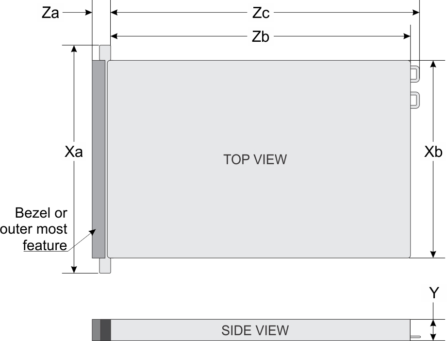
| Xa | Xb | Y | Za | Zb* | Zc |
|---|---|---|---|---|---|
| 482.0 mm (18.9 inches) | 448.0 mm (17.63 inches) | 86.8 mm (3.41 inches) | With bezel: 35.93 mm (1.41 inches) Without bezel: 22.0 mm (0.866 inches) | 810.264 mm (31.9 inches) | 844.826mm (33.260 inches) |
System weight
| System configuration | Maximum weight (with all drives/SSDs) |
|---|---|
| 24+2 x 3.5-inch drives | 40 kg (88.2 lb) |
Processor specifications
| Supported processor | Number of supported processors |
|---|---|
| 2nd generation Intel Xeon Scalable Processor | Two |
Supported operating systems
The Dell EMC PowerEdge R740xd2 supports the following operating systems:
- Canonical Ubuntu LTS
- Citrix XenServer
- Microsoft Windows Server
- Red Hat Enterprise Linux
- SUSE Linux Enterprise Server
- VMware ESXi
PSU specifications
| PSU | Class | Heat dissipation (maximum) | Frequency | Voltage | AC | DC | Current | |
|---|---|---|---|---|---|---|---|---|
| High line 100–240 V | Low line 100–120 V | |||||||
| 1100 W AC | Platinum | 4100 BTU/hr | 50/60 Hz | 100–240 V AC, autoranging | 1100 W | 1050 W | NA | 12 A–6.5 A |
| 1100 W Mixed Mode HVDC (for China and Japan only) | Platinum | 4416 BTU/hr | 50/60 Hz | 100–240 V AC, autoranging | 1100 W | NA | NA | 12 A–6.5 A |
| Platinum | 4416 BTU/hr | NA | 200–380 V DC, autoranging | NA | NA | 1100 W | 6.4 A–3.2 A | |
| 750 W AC | Platinum | 2891 BTU/hr | 50/60 Hz | 100–240 V AC, autoranging | 750 W | NA | NA | 10 A–5 A |
| 750 W Mixed Mode | Platinum | 2902 BTU/hr/ | 50/60 Hz | 100–240 V AC, autoranging | 750 W | NA | NA | 10 A–5 A |
| Platinum (For China only) | 2902 BTU/hr/ | NA | 240 V DC, autoranging | NA | NA | 750 W | 5 A | |
| 750 W Mixed Mode HVDC (for China only) | Platinum | 2902 BTU/hr/ | 50/60 Hz | 100–240 V AC, autoranging | 750 W | NA | NA | 10 A–5 A |
| Platinum | 2902 BTU/hr | NA | 240 V DC, autoranging | NA | NA | 750 W | 4.5 A | |
Cooling fans specifications
| Storage | PSU type | Processor count | Fan 1 | Fan 2 | Fan 3 | Fan 4 | Fan 5 | Fan 6 |
|---|---|---|---|---|---|---|---|---|
| 24+2 x 3.5-inch or 24 x 3.5-inch. | Redundant PSUs only | 1 | Required | Required | Required | Required | Required | Required |
| 2 | Required | Required | Required | Required | Required | Required |
System battery specifications
The Dell EMC PowerEdge R740xd2 system supports CR 2032 3.0-V lithium coin cell system battery.
PCIe Expansion card riser specifications
The Dell EMC PowerEdge R740xd2 system supports up to three PCI express (PCIe) generation expansion cards that can be installed on the system board and expansion card risers.
| Processor 1 | Processor 2 | PCH | ||||||||
|---|---|---|---|---|---|---|---|---|---|---|
| PCie slots on the riser | Card support | Riser 2 (LOM riser) | Right riser | Butterfly riser | On Planar | Internal riser | Left riser | On Planar | On Planar | |
| PCIe slot-1 | Unique to Dell | x8 | ||||||||
| PCIe slot-2 | Low profile-half length | x16 | ||||||||
| PCIe slot-2 | Full height-half length | x16 | x8 or x16 | |||||||
| PCIe slot-3 | Low profile-half length | x8 | x16 | |||||||
| PCIe slot-4 | Low profile-half length | x16 | ||||||||
| PCIe slot-5
NOTE PCIe slot 5 has open backend and bigger PCIe card connections can be inserted in this slot.
|
Low profile-half length | x4 | ||||||||
| PCIe slot-6 | Low profile-half length | x4 | ||||||||
Memory specifications
| DIMM type | DIMM rank | DIMM capacity | Single processor | Dual processors | ||
|---|---|---|---|---|---|---|
| Minimum RAM | Maximum RAM | Minimum RAM | Maximum RAM | |||
| RDIMM | Single rank | 8 GB | 8 GB | 80 GB | 16 GB | 128 GB |
| Dual rank | 16 GB | 16 GB | 160 GB | 32 GB | 256 GB | |
| Dual rank | 32 GB | 32 GB | 320 GB | 64 GB | 512 GB | |
Storage controller specifications
| Internal controllers | External controllers |
|---|---|
|
|
Drives
| Chassis options | Configurations |
|---|---|
| Twenty-four drive chassis | Up to twenty-four 3.5-inch (SATA or Nearline SAS drives) front accessible drives in slots 0 through 23 and
Up to eight 2.5-inch (SAS, SATA SSDs) front accessible drives can be installed from slots 16 through 23. |
| Twenty-four front + two rear drive chassis | Up to twenty-four 3.5 inch (SATA or Nearline SAS drives) front accessible drives in slots 0 through 23 and up to two 3.5-inch SAS/SATA rear accessible drives.
NOTE For single PERC configuration, it is slot 24 to slot 25. For dual PERC configuration including S140 software RAID, it is slot 0 to slot 1.
|
Hard drives configurations
| Chassis options | Configurations |
|---|---|
| Twenty-four 3.5-inch (12+12 with single PERC) |
|
| Twenty-four 3.5-inch front + two 3.5-inch rear ( 12 + 12 + 2 with single PERC) |
|
| Twenty-four 3.5-inch front + two 3.5-inch rear ( 12 + 12 + 2 rear chipset SATA) |
|
| Twenty-four 3.5-inch front + two 3.5-inch rear (Dual PERC: Bay 1 and 2 on first PERC, Bay 0 on second PERC) |
|
USB ports specifications
| Front | Rear | Internal | |||
|---|---|---|---|---|---|
| USB port type | No. of ports | USB port type | No. of ports | USB port type | No. of ports |
| USB 2.0-compliant port | One | USB 3.0-compliant ports | Two | Internal USB 3.0-compliant port | One |
| Micro USB 2.0-compliant port for iDRAC Direct NOTE The micro USB 2.0 compliant
port can only be used as an iDRAC Direct
or a management port. | One | ||||
NIC ports specifications
Serial connector specifications
The Dell EMC PowerEdge R740xd2 system supports one serial connector on the back panel, which is a 9-pin connector, Data Terminal Equipment (DTE), 16550-compliant.
VGA ports specifications
The Dell EMC PowerEdge R740xd2 system supports one 15-pin VGA ports, on the rear of the system.
IDSDM module
- vFlash or
- vFlash and IDSDM
| IDSDM card | vFlash card |
|---|---|
|
|
Video specifications
| Resolution | Refresh rate (Hz) | Color depth (bits) |
|---|---|---|
| 1024 x 768 | 60 | 8, 16, 32 |
| 1280 x 800 | 60 | 8, 16, 32 |
| 1280 x 1024 | 60 | 8, 16, 32 |
| 1360 x 768 | 60 | 8, 16, 32 |
| 1440 x 900 | 60 | 8, 16, 32 |
| 1600 x 900 | 60 | 8, 16, 32 |
| 1600 x 1200 | 60 | 8, 16, 32 |
| 1680 x 1050 | 60 | 8, 16, 32 |
| 1920 x 1080 | 60 | 8, 16, 32 |
| 1920 x 1200 | 60 | 8, 16, 32 |
Environmental specifications
| Temperature | Specifications |
|---|---|
| Storage | -40–65°C (-40–149°F) |
| Continuous operation (for altitude less than 950 m or 3117 ft) | 10–30°C (50–86°F) with no direct sunlight on the equipment |
| Fresh air | For information about fresh air, see the Expanded operating temperature section. |
| Maximum temperature gradient (operating and storage) | 20°C/h (36°F/h) |
| Relative humidity | Specifications |
|---|---|
| Storage | 5% to 95% RH with 33°C (91°F) maximum dew point.
Atmosphere must be noncondensing at all times. |
| Operating | 10% to 80% RH with 29°C (84.2°F) maximum dew point. |
| Maximum vibration | Specifications |
|---|---|
| Operating | 0.26 Grms at 5 Hz to 350 Hz (all operation orientations) |
| Storage | 1.88 Grms at 10 Hz to 500 Hz for 15 minutes (all six sides tested) |
| Maximum shock pulse | Specifications |
|---|---|
| Operating | Six consecutively executed shock pulses in the positive and negative x, y, and z axis of 6 G for up to 11 ms. |
| Storage | Six consecutively executed shock pulses in the positive and negative x, y, and z axis (one pulse on each side of the system) of 71 G for up to 2 ms. |
| Maximum altitude | Specifications |
|---|---|
| Operating | 3048 m (10,000 ft) |
| Storage | 12,000 m (39,370 ft) |
| Operating temperature derating | Specifications |
|---|---|
| Up to 30°C (86°F) | Maximum temperature is reduced by 1°C/300 m (1°F/547 ft), above 950 m (3,117 ft). |
| 30–40°C (86–104°F) | Maximum temperature is reduced by 1°C/175 m (1°F/319 ft), above 950 m (3,117 ft). |
| 40–45°C (104–113°F) | Maximum temperature is reduced by 1°C/125 m (1°F/228 ft), above 950 m (3,117 ft). |
Standard operating temperature
| Standard operating temperature | Specifications |
|---|---|
| Continuous operation (for altitude less than 950 m or 3117 ft) | 10°C to 30°C (50°F to 86°F) with no direct sunlight on the equipment. |
Thermal restrictions
- System must operate at temperature below 30°C.
- All fans installed in the system must be from the same manufacturer.
- Fresh air condition is not supported.
- 140W processors are not supported in rear drive configuration.
- Non Dell qualified or certified processors are not supported.
- LRDIMM is not supported.
- 10 GbE / 25 GbE OCPs require PCIe shroud with rear drive configuration if there is no PCIe card installed.
- Butterfly without riser configuration cannot support 10GbE / 25GbE OCP because PCIe shroud cannot be installed.
- Drive bays should not be in service position for more than 5 minutes because of thermal concerns. When the drive bay is open for more than five minutes, the cooling fans spin at a higher speed to provide extra cooling to the system. Thus system health status changes from the normal to critical state, and system event The BP1 drive bay is kept open for an extended period of time is logged.
- GPGPU card is not supported.
- Non Dell certified peripheral cards are not supported.
- Expansion card and riser installation must follow specific Expansion card installation guidelines.
- Mellanox CX-5 dual port 100G - QSPF PCIe adapter cable is restricted to Dell NW QSPF28 Direct attach cables and Finisar 100G 85C optic cables. Non Dell certified cables are not supported.
| Configuration | Maximum no.of processors supported | DIMM blanks | Heat Sink | Type of Air shroud | Fan | ||
|---|---|---|---|---|---|---|---|
| Quantity | Model | ||||||
| Butterfly Configuration | No riser | 1 or 2 processors | <=140 W | Required | Processor 1 : Standard heat sink
Processor 2: 1.5 U HPR heatsink |
2U Air shroud | 6 x High Performance fans |
| With Butterfly Riser | |||||||
| Rear Module Configuration | Right Riser for 1x FH adapter card | 1 or 2 processors | <=125 W | Processor 1 : Standard heat sink
Processor 2: 1 U HPR heatsink |
2U Air shroud for Rear 3.5" X 2 HDD | ||
| Right Riser + Left Riser for 2x LP adapter cards | |||||||
| Thermal Cooling Tier level | Bus width | Full height Cards | Application Restriction (Configuration Type / PCIe slot) | Half height Cards | Application Restriction (Configuration Type / PCIe slot) |
|---|---|---|---|---|---|
| 5 | x8 | - | Rear HDD Module Configuration / Slot# 2 | QLOGIC 10G Dual port BT, QLOGIC 25G Dual port SFP |
|
| 6 | Mellanox 40G Dual Port CXP, QSFP, Solarflare 10G Dual Port SF852P, Solarflare 10G Dual Port SF852X | Mellanox 40G Dual Port CXP QSF, Solarflare 10G Dual Port SF852X, Solarflare 10G Dual Port SF852P |
|
||
| Mellanox 40G Dual Port CXP, QSFP |
|
||||
| 10 | QLOGIC 10G Quad port QLGX | QLOGIC 10G Quad port QLGX |
|
||
| 8 | x4 | - | - | Intel NVME P4800X | Butterfly Riser Configuration / Slot# 3 |
Particulate and gaseous contamination specifications
| Particulate contamination | Specifications |
|---|---|
| Air filtration | Data center air filtration as defined by ISO Class
8 per ISO 14644-1 with a 95% upper confidence limit. NOTE This condition applies
to data center environments only. Air filtration requirements do not
apply to IT equipment designed to be used outside a data center, in
environments such as an office or factory floor. NOTE Air entering the data
center must have MERV11 or MERV13 filtration. |
| Conductive dust | Air must be free of conductive dust, zinc whiskers,
or other conductive particles. NOTE This condition applies
to data center and non-data center environments. |
| Corrosive dust |
NOTE This condition
applies to data center and non-data center environments. |
| Gaseous contamination | Specifications |
|---|---|
| Copper coupon corrosion rate | <300 Å/month per Class G1 as defined by ANSI/ISA71.04-1985. |
| Silver coupon corrosion rate | <200 Å/month as defined by AHSRAE TC9.9. |