





























Chassis dimensions
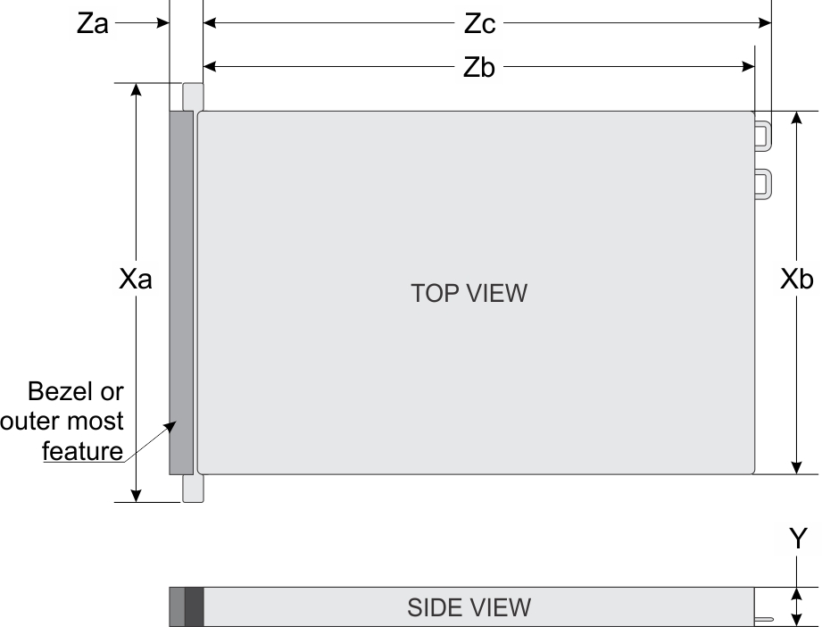
| System configurations | Xa | Xb | Y | Za | Zb* | Zc |
|---|---|---|---|---|---|---|
| 4 x 3.5-inches or 10 x 2.5-inches | 482.0 mm (18.97 inches) | 434.0 mm (17.08 inches) | 42.8 mm (1.68 inches) | With bezel: 35.84 mm (1.4 inches) Without bezel: 22.0 mm (0.87 inches) | 657.25 mm (25.87 inches) | 692.62 mm (27.26 inches) |
| 8 x 2.5-inches | 482.0 mm (18.97 inches) | 434.0 mm (17.08 inches) | 42.8 mm (1.68 inches) | With bezel: 35.84 mm (1.4 inches) Without bezel: 22.0 mm (0.87 inches) | 606.47 mm (23.87 inches) | 641.85 mm (25.26 inches) |
System weight
| System configuration | Maximum weight (with all drives) |
|---|---|
| 4 x 3.5-inch configuration | 16.75 kg (36.92 lb) |
| 8 x 2.5-inch configuration | 15.6 kg (34.39 lb) |
| 10 x 2.5-inch configuration | 15.8 kg (34.83 lb) |
Processor specifications
| Supported processor | Number of processors supported |
|---|---|
| AMD EYPC 7002 and 7003 series processor | One |
PSU specifications
| PSU | Class | Heat dissipation (maximum) | Frequency | Voltage | Current |
|---|---|---|---|---|---|
| 550 W AC | Platinum | 2107 BTU/hr | 50/60 Hz | 100-240 V AC,autoranging | 7.4 A - 3.7 A |
| 700 W AC | Platinum | 2107 BTU/hr | 50/60 Hz | 100-240 V AC,autoranging | 7.4 A - 3.7 A |
Supported operating systems
The PowerEdge R6515 supports the following operating systems:
- Canonical Ubuntu Server LTS
- Citrix Xen Hypervisor
- Microsoft Windows Server with Hyper-V
- Red Hat Enterprise Linux
- SUSE Linux Enterprise Server
- VMware vSAN/ESXi
Cooling fans specifications
The PowerEdge R6515 system supports both the Standard fan (STD fan) and High Performance fan (HPR fan) and requires all six fans to be installed.
System battery specifications
The PowerEdge R6515 system supports CR 2032 3.0-V lithium coin cell system battery.
Expansion card riser specifications
| PCIe slot | Riser | PCIe slot height | PCIe slot length | Slot width |
|---|---|---|---|---|
| Slot 2 | Riser 1A | Low-profile | Half-length | x16 (Gen 3) |
| Slot 3 | Riser 2 | Low-profile | Half-length | x16 (Gen 4) |
Memory specifications
| DIMM type | DIMM rank | DIMM capacity | Minimum RAM | Maximum RAM |
|---|---|---|---|---|
| RDIMM | Single rank | 8 GB | 8 GB | 128 GB |
| Dual rank | 16 GB | 16 GB | 256 GB | |
| 32 GB | 32 GB | 512 GB | ||
| 64 GB | 64 GB | 1 TB | ||
| 3DS LRDIMM | Octa rank | 128 GB | 128 GB | 2 TB |
| Memory module sockets | Speed |
|---|---|
| Sixteen 288-pin | 3200 MT/s, 2933 MT/s, 2666 MT/s |
Storage controller specifications
| Internal controllers | External controllers |
|---|---|
|
|
Drives
- Up to 4 x 3.5-inch (SAS, SATA or SSD) front accessible drives in slot 0 to 3
- Up to 8 x 2.5-inch (SAS, SATA or SSD) front accessible drives in slot 0 to 7
- Up to 10 x 2.5-inch drives front accessible drives (with 8 SAS/SATA drives in slot 0 to 7 + 2 NVMe drives in slot 8 to 9)
- Up to 10 x 2.5-inch front accessible NVMe drives in slot 0 to 9
Optical drives
| Supported drive type | Supported number of drives |
|---|---|
| Dedicated SATA DVD-ROM drive or DVD +/-RW drive | One |
USB ports specifications
| Front | Rear | Internal | |||
|---|---|---|---|---|---|
| USB port type | No. of ports | USB port type | No. of ports | USB port type | No. of ports |
| USB 2.0-compliant port | One | USB 3.0-compliant ports | Two | Internal USB 3.0-compliant port | One |
| Micro USB 2.0-compliant port for iDRAC Direct | One | ||||
LOM riser card specifications
You can install one LOM riser card. The supported LOM riser options are:
- 2 x 1 Gb Base-T
- 2 x 10Gb Base-T
- 2 x 10Gb SFP+
- 2 x 25Gb SFP+
- You can install up to two PCIe add-on NIC cards.
- For information about Linux network performance settings, see the Linux Network Tuning Guide for AMD EPYC Processor Based Servers white paper at AMD.com
Serial connector specifications
The PowerEdge R6515 system supports one serial connector on the back panel, which is a 9-pin connector, Data Terminal Equipment (DTE), 16550-compliant.
VGA ports specifications
The PowerEdge R6515 system supports two 15-pin VGA ports one each on the front and back panels.
IDSDM
- 16 GB
- 32 GB
- 64 GB
Video specifications
| Resolution | Refresh rate (Hz) | Color depth (bits) |
|---|---|---|
| 1024 x 768 | 60 | 8, 16, 32 |
| 1280 x 800 | 60 | 8, 16, 32 |
| 1280 x 1024 | 60 | 8, 16, 32 |
| 1360 x 768 | 60 | 8, 16, 32 |
| 1440 x 900 | 60 | 8, 16, 32 |
| Resolution | Refresh rate (Hz) | Color depth (bits) |
|---|---|---|
| 1024 x 768 | 60 | 8, 16, 32 |
| 1280 x 800 | 60 | 8, 16, 32 |
| 1280 x 1024 | 60 | 8, 16, 32 |
| 1360 x 768 | 60 | 8, 16, 32 |
| 1440 x 900 | 60 | 8, 16, 32 |
| 1600 x 900 | 60 | 8, 16, 32 |
| 1600 x 1200 | 60 | 8, 16, 32 |
| 1680 x 1050 | 60 | 8, 16, 32 |
| 1920 x 1080 | 60 | 8, 16, 32 |
| 1920 x 1200 | 60 | 8, 16, 32 |
Environmental specifications
Operational climatic range category A2
| Allowable continuous operations | |
|---|---|
| Temperature ranges for altitude <900 meters (<2,953 feet) | 10 to 35°C (50 to 95°F) with no direct sunlight on the platform |
| Humidity percent ranges (Non-condensing at all times) | 8% RH with -12°C minimum dew point to 80% RH with 21°C (69.8°F) maximum dew point |
| Operational altitude de-rating | Maximum temperature is reduced by 1°C/300 meters (1.8°F/984 feet) above 900 meters (2,953 feet) |
Operational climatic range category A3
| Allowable continuous operations | |
|---|---|
| Temperature ranges for altitude <900 meters (<2,953 ft) | 5°C- 40°C (41°F-104°F) with no direct sunlight on the platform |
| Humidity percent ranges (Noncondensing at all times) | 8% RH with -12°C minimum dew point to 85% RH with 24°C (75.2°F) maximum dew point |
| Operational altitude de-rating | Maximum temperature is reduced by 1°C/175 meters (1.8°F/574 feet) above 900 meters (2,953 feet) |
Shared requirements across all categories
| Allowable operations | |
|---|---|
| Maximum temperature gradient (applies to both operation and nonoperation) | 20°C in an hour* (36°F in an hour) and 5°C in 15 minutes (9°F in 15 minutes), 5°C in an hour* (9°F in an hour) for tape hardware |
| Nonoperational temperature limits | -40°C-65°C (-40°F-149°F) |
| Nonoperational humidity limits | 5% to 95% RH with 27°C (80.6°F) maximum dew point |
| Maximum nonoperational altitude | 12,000 meters (39,370 feet) |
| Maximum operational altitude | 3,048 meters (10,000 feet) |
*: Per ASHRAE thermal guidelines, these are not instantaneous rates of temperature change.
| Maximum vibration | Specifications |
|---|---|
| Operating | 0.26 Grms at 5 Hz to 350 Hz (all operation orientations) |
| Storage | 1.88 Grms at 10 Hz to 500 Hz for 15 minutes (all six sides tested) |
| Maximum shock pulse | Specifications |
|---|---|
| Operating | 24 run shock pulses in the positive and negative x, y, and z axis of 6 G for up to 11 ms. (4 pulse on each side of the system) |
| Storage | Six consecutively run shock pulses in the positive and negative x, y, and z axis (one pulse on each side of the system) of 71 G for up to 2 ms. |
Particulate and gaseous contamination specifications
| Particulate contamination | Specifications |
|---|---|
| Air filtration |
Data center air filtration as defined by ISO Class 8 per ISO 14644-1 with a 95% upper confidence limit. NOTE This condition applies to data center environments only. Air filtration requirements do not apply to IT equipment designed to be used outside a data center, in environments such as an office or factory floor.
NOTE Air entering the data center must have MERV11 or MERV13 filtration.
NOTE Air filtering can also be accomplished by filtering room air with MERV8 filter per ANSI/ASHARE Standard 127.
|
|
Conductive dust |
Air must be free of conductive dust, zinc whiskers, or other conductive particles. NOTE This condition applies to data center and non-data center environments.
NOTE Common sources of conductive dust include manufacturing processes, and zinc whiskers from the plating on the bottom of raised floor tiles.
|
|
Corrosive dust |
NOTE This condition applies to data center and non-data center environments.
|
| Gaseous contamination | Specifications |
|---|---|
| Copper Coupon Corrosion rate | <300 Å/month per Class G1 as defined by ANSI/ISA71.04-2013 |
| Silver Coupon Corrosion rate | <200 Å/month as defined by ANSI/ISA71.04-2013 |
Thermal restriction matrix
| Configuration | 4 x 3.5-inch | 8 x 2.5-inch | 10 x 2.5-inch drives (NVMe) |
|---|---|---|---|
| Processor TDP | |||
| 120 W | STD fan
STD HSK |
STD fan
STD HSK |
HPR fan*
STD HSK |
| 155 W | STD fan
STD HSK |
STD fan
STD HSK |
HPR fan*
STD HSK |
| 180 W | STD fan
HPR HSK |
STD fan
HPR HSK |
HPR fan*
HPR HSK |
| 200 W | STD fan
HPR HSK |
STD fan
HPR HSK |
HPR fan*
HPR HSK |
| 225 W | HPR fan
HPR HSK |
HPR fan
HPR HSK |
HPR fan*
HPR HSK |
| 240 W | HPR fan
HPR HSK |
HPR fan
HPR HSK |
HPR fan*
HPR HSK |
| 280 W | HPR fan
HPR HSK with DIMM Blank |
HPR fan
HPR HSK with DIMM Blank |
Not supported |
| 280 W - 64C/32C | HPR fan
HPR HSK with DIMM Blank |
HPR fan
HPR HSK with DIMM Blank |
Not supported |
| Riser configurations | Configuration type and ambient temperature support | ||
|---|---|---|---|
| 4 x 3.5-inch drives | 8 x 2.5-inch drives | 10 x 2.5-inch drives (NVMe) | |
| 2 LP | 2 LP | 2 LP | |
| Ambient = 30°C | |||
| Slot 2 | HPR fan | HPR fan | NA |
| Slot 3 | HPR fan | HPR fan | HPR fan + NVMe drives from slot 6-9 + SAS or SATA drives from slot 0-5 |
| Label | Description |
|---|---|
| STD | Standard |
| HPR | High performance |
| HSK | Heat sink |
| LP | Low profile |
Thermal restriction for ASHRAE A3/Fresh air environment
- Processor TDP equal or greater than 180 W are not supported.
- 128 GB or greater capacity LRDIMMs are not supported.
- Redundant power supply configuration is required, but PSU failure is not supported
- Non-Dell qualified peripheral cards greater than 25 W are not supported.
- GPU card is not supported.
- PCIe SSD is not supported.
Thermal restriction for ASHRAE A4/Fresh air environment
- Processor TDP equal or greater than 155 W are not supported within A4.
- 128 GB or greater capacity LRDIMMs are not supported within A4.
- Two PSUs are required in redundant mode, but PSU failure is not supported.
- Non Dell qualified peripheral cards and/or peripheral cards greater than 25W are not supported.
- GPU is not supported within A4.
- PCIeSSD is not supported within A4.
- 25G OCP is not supported within A4.
Other thermal restrictions
- SolarFlare, Mellanox CX4/CX5/CX6, P4800 AIC can only support up to 35°C ambient.
- Mellanox CX6 on 10x2.5-inch configuration can only support on slot 3.
- 25G OCP card does not support with 128 GB LRDIMM on 10 x 2.5-inch configuration.
- HPR fan is required with 128 GB LRDIMM.
- T4 GPGPU is not supported with 128 GB LRDIMM.
- T4 GPGPU supports up to 30°C ambient temperature with HPR fans and 4 x 3.5-inch or 8 x 2.5-inch configurations.
- T4 GPGPU supports up to 30°C ambient temperature with HPR fan and 10 x 2.5-inch configuration (NVMe(slot 6-9) and SAS or SATA drives (slot 0-5)) on slot 3 only.