





























System dimensions
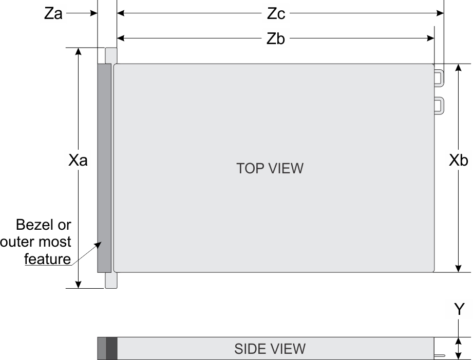
| System | Xa | Xb | Y | Za (with bezel) | Za (without bezel) | Zb* | Zc |
|---|---|---|---|---|---|---|---|
4 x 3.5-inches or 10 x 2.5-inches | 482.0 mm (18.97-inches) | 434.0 mm (17.08-inches) | 42.8 mm (1.68-inches) | 35.84 mm (1.41-inches) | 22.0 mm (0.87-inches) | 733.82 mm (29.61-inches) | 772.67 mm (30.42-inches) |
| 8 x 2.5-inches | 482.0 mm (18.97-inches) | 434.0 mm (17.08-inches) | 42.8 mm (1.68-inches) | 35.84 mm (1.41-inches) | 22.0 mm (0.87-inches) | 683.05 mm (26.89-inches) | 721.91 (28.42-inches) |
Chassis weight
| System | Maximum weight (with all hard drives/SSDs) |
|---|---|
| PowerEdge R640 | 21.9 kg
(48.28 lbs) |
Processor specifications
Cooling fan specifications
The cooling fans are integrated into the system to dissipate the heat generated by the functioning of the system. These fans provide cooling for the processors, expansion cards, and memory modules.
Your system supports up to eight standard or high performance cooling fans.
- High performance fans can be identified by a blue label on top of the cooling fan.
- Mixing of standard and high performance cooling fans is not supported.
- Each fan is listed in the systems management software, referenced by the respective fan number. If there is a problem with a particular fan, you can easily identify and replace the proper fan by noting the fan number on the system.
PSU specifications
The PowerEdge R640 system supports up to two AC or DC power supply units (PSUs).
| PSU | Class | Heat dissipation (maximum) | Frequency | Voltage |
|---|---|---|---|---|
| 495 W AC | Platinum | 1908 BTU/hr | 50/60 Hz | 100–240 V AC, autoranging |
| 750 W AC | Platinum | 2891 BTU/hr | 50/60 Hz | 100–240 V AC, autoranging |
| 750 W Mixed Mode AC | Platinum | 2891 BTU/hr | 50/60 Hz | 100–240 V AC, 10 A - 5 A |
| 750 W AC | Titanium | 2843 BTU/hr | 50/60 Hz | 200–240 V AC |
| 750 W Mixed Mode HVDC (for China only) | Platinum | 2891 BTU/hr | 50/60 Hz | 100–240 V AC |
| 750 W Mixed Mode DC (for China only) | N/A | 2891 BTU/hr | 50/60 Hz | 240 V DC, 4.5 A |
| 1100 W DC | N/A | 4416 BTU/hr | 50/60 Hz | –(48–60) V DC |
| 1100 W Mixed Mode HVDC (for China and Japan only) | Platinum | 4100 BTU/hr | 50/60 Hz | 100–240 V AC and 200–380 V DC |
| 1100 W AC | Platinum | 4100 BTU/hr | 50/60 Hz | 100–240 V AC |
| 1600 W AC | Platinum | 6000 BTU/hr | 50/60 Hz | 100–240 V AC |
| 1600 W AC | Titanum | 5970 BTU/hr | 50/60 Hz | 200–240 V AC |
System battery specifications
The PowerEdge R640 system supports CR 2032 lithium coin cell system battery.
Expansion bus specifications
The PowerEdge R640 system supports PCI express (PCIe) generation 3 expansion cards, which are installed on the system, using expansion card risers. This system supports 1A, 2A, 1B, and 2B expansion card risers.
- The expansion card riser slots are not hot-pluggable.
- Internal cable connectors are not hot-pluggable.
Memory specifications
| DIMM type | DIMM rank | DIMM capacity | Single processor | Dual processors | ||
|---|---|---|---|---|---|---|
| Minimum RAM | Maximum RAM | Minimum RAM | Maximum RAM | |||
| LRDIMM | Octa rank | 512 GB | 512 GB | 6 TB | 1024 GB | 12 TB |
| 256 GB | 256 GB | 3 TB | 512 GB | 6 TB | ||
| 128 GB | 128 GB | 1.5 TB | 256 GB | 3 TB | ||
| Quad rank | 64 GB | 64 GB | 768 GB | 128 GB | 1.5 TB | |
| RDIMM | Single rank | 8 GB | 8 GB | 96 GB | 16 GB | 192 GB |
| Dual rank | 16 GB | 16 GB | 192 GB | 32 GB | 384 GB | |
| 32 GB | 32 GB | 384 GB | 64 GB | 768 GB | ||
| 64 GB | 64 GB | 768 GB | 128 GB | 1536 GB | ||
| NVDIMM-N | Single rank | 16 GB | Not supported with single processor | Not supported with single processor | RDIMM: 192 GB | RDIMM: 384 GB |
| NVDIMM-N: 16 GB | NVDIMM-N: 192 GB | |||||
| PMem | NA | 128 GB | RDIMM: 64 GB | RDIMM: 384 GB | RDIMM: 128 GB | LRDIMM: 1536 GB |
| PMem: 128 GB | PMem: 768 GB | PMem: 128 GB | PMem: 1536 GB | |||
| NA | 256 GB | NA | NA | RDIMM: 192 GB | LRDIMM: 1536 GB | |
| NA | NA | PMem: 2048 GB | PMem: 3072 GB | |||
| NA | 512 GB | NA | NA | RDIMM: 384 GB | RDIMM: 1536 GB | |
| NA | NA | PMem: 4096 GB | PMem: 6144 GB | |||
Storage controller specifications
The PowerEdge R640 system supports:
- Internal storage controller cards: PowerEdge RAID Controller (PERC) H330, H350, HBA350i, H730P, H740P, H750 (adapter only), Software RAID (SWRAID) S140.
- Boot Optimized Storage Subsystem: HWRAID 2 x M.2 SSDs 240 GB, 480 GB.
- The card supports up to two 6 Gbps M.2 SATA drives. The BOSS adapter card has a x8 connector using PCIe gen 2.0 x2 lanes, available only in the low-profile and half-height form factor.
- External PERC (RAID): H840
- 12Gbps SAS HBAs (non-RAID):
- External- 12 Gbps SAS HBA (non-RAID), HBA355e (adapter only, non-RAID)
- Internal- HBA330 (non-RAID), HBA350i (non-RAID)
Hard drive specifications
The PowerEdge R640 supports :
- Up to ten 2.5 inch, hot swappable SAS, SATA, SAS/SATA SSD, NVMe (up to 8x) or Nearline SAS hard drives with up to 2 x 2.5 inch hot swappable SAS, SATA, SAS/SATA SSD, NVMe or Nearline SAS hard drives supported at the back of the system
- Up to eight 2.5 inch, hot swappable SAS, SATA, SAS/SATA SSD, or Nearline SAS hard drives
- Up to four 3.5 inch, hot swappable hard drives with up to 2 x 2.5 inch hot swappable SAS, SATA, SAS/SATA SSD, or Nearline SAS hard drives supported at the back of the system
Optical drive
Certain configurations of the system support one optional SATA DVD-ROM drive or DVD+/-RW drive.
USB ports
| System | Front panel | Back panel | Internal |
|---|---|---|---|
| Four hard drive systems | One 4-pin, USB 2.0-compliant ports | Two 9-pin, USB 3.0-compliant ports | One 9-pin, USB 3.0-compliant ports |
| One 5-pin micro USB 2.0 management port
NOTE: The micro USB 2.0-compliant port on the front panel can only be used as an iDRAC Direct or a management port.
|
N/A | N/A | |
| Eight hard drive systems | One 4-pin, USB 2.0-compliant ports | Two 9-pin, USB 3.0-compliant ports
NOTE: One optional USB 3.0-compliant port on the front panel for 4 x 3.5 and 8 x 2.5 inch hard drive
systems.
|
One 9-pin, USB 3.0-compliant ports |
| One 5-pin micro USB 2.0 management port | N/A | N/A | |
| Ten hard drive systems | One 4-pins, USB 2.0-compliant port | Two 9-pin, USB 3.0-compliant ports | One 9-pin, USB 3.0-compliant ports |
| One 5-pin micro USB 2.0 management port | N/A | N/A |
NIC ports
- Four RJ-45 ports that support 10, 100 and 1000 Mbps
- Four RJ-45 ports that support 100 M, 1 G and 10 Gbps
- Four RJ-45 ports, where two ports support maximum of 10 G and the other two ports maximum of 1 Gbps
- Two RJ-45 ports that support up to 1 Gbps and 2 SFP+ ports that support up to 10 Gbps
- Four SFP+ ports that support up to 10 Gbps
- Two SFP28 ports that support up to 25 Gbps
Serial port
The PowerEdge R640 system supports one serial port on the back panel. This port is a 9-pin connector, Data Terminal Equipment (DTE), 16550-compliant.
VGA ports
The Video Graphic Array (VGA) port enables you to connect the system to a VGA display. The PowerEdge R640 system supports one 15-pin VGA port on the front and back of system.
Video specifications
The PowerEdge R640 system supports integrated Matrox G200eW3 graphics controller with 16 MB of video frame buffer .
| Resolution | Refresh rate (Hz) | Color depth (bits) |
|---|---|---|
| 640 x 480 | 60, 70 | 8, 16, 32 |
| 800 x 600 | 60, 75, 85 | 8, 16, 32 |
| 1024 x 768 | 60, 75, 85 | 8, 16, 32 |
| 1152 x 864 | 60, 75, 85 | 8, 16, 32 |
| 1280 x 1024 | 60, 75 | 8, 16, 32 |
| 1440 x 900 | 60 | 8, 16, 32 |
| 1920 x 1200 | 60 | 8, 16, 32 |
IDSDM or vFlash card
The PowerEdge R640 system supports Internal Dual SD module (IDSDM) and vFlash card. In the 14th generation of PowerEdge servers, IDSDM and vFlash card are combined into a single module, and are available in the following options:
- vFlash or
- vFlash and IDSDM
The IDSDM/vFlash card can be connected in a Dell-proprietary PCIe x1 slot using a USB 3.0 interface to host. IDSDM/vFlash module supports two MicroSD cards for IDSDM and one card for vFlash. The MicroSD card capacity for IDSDM are 16, 32, or 64 GB, while for vFlash the MicroSD card capacity is 16 GB. The IDSDM or vFlash module combines the IDSDM or vFlash features into a single module.
Environmental specifications
| Temperature | Specifications |
|---|---|
| Storage | –40°C to 65°C (–40°F to 149°F) |
| Continuous operation (for altitude less than 950 m or 3117 ft) | 10°C to 35°C (50°F to 95°F) with no direct sunlight on the equipment. NOTE: Maximum of 205 W, 28 core processor is supported in systems with eight 2.5 inch processor direct attached PCIe SSD drives, and three PCIe slot chassis. NOTE: Certain configurations may have ambient temperature restrictions. For more information see the Ambient temperature limitations section. |
| Fresh air | For information about fresh air, see Expanded Operating Temperature section. |
| Maximum temperature gradient (operating and storage) | 20°C/h (68°F/h) |
| Relative humidity | Specifications |
|---|---|
| Storage | 5% to 95% RH with 33°C (91°F) maximum dew point. Atmosphere must be non-condensing at all times. |
| Operating | 10% to 80% relative humidity with 29°C (84.2°F) maximum dew point. |
| Maximum vibration | Specifications |
|---|---|
| Operating | 0.26 Grms at 5 Hz to 350 Hz (all operation orientations). |
| Storage | 1.88 Grms at 10 Hz to 500 Hz for 15 min (all six sides tested). |
| Maximum shock | Specifications |
|---|---|
| Operating | Six consecutively executed shock pulses in the positive and negative x, y, and z axes of 6 G for up to 11 ms. |
| Storage | Six consecutively executed shock pulses in the positive and negative x, y, and z axes (one pulse on each side of the system) of 71 G for up to 2 ms. |
| Maximum altitude | Specifications |
|---|---|
| Operating | 3048 m (10,000 ft) |
| Storage | 12,000 m (39,370 ft) |
| Operating temperature de-rating | Specifications |
|---|---|
| Up to 35°C (95°F) | Maximum temperature is reduced by 1°C/300 m (1°F/547 ft) above 950 m (3,117 ft). |
| 35°C to 40°C (95°F to 104°F) | Maximum temperature is reduced by 1°C/175 m (1°F/319 ft) above 950 m (3,117 ft). |
| 40°C to 45°C (104°F to 113°F) | Maximum temperature is reduced by 1°C/125 m (1°F/228 ft) above 950 m (3,117 ft). |
Standard operating temperature
| Standard operating temperature | Specifications |
|---|---|
| Continuous operation (for altitude less than 950 m or 3117 ft) | 10°C to 35°C (50°F to 95°F) with no direct sunlight on the equipment. |
Expanded operating temperature
| Expanded operating temperature | Specifications |
|---|---|
| ≤ 10% of annual operating hours | 5°C–40°C at 5% to 85% RH with 29°C dew point.
NOTE: Outside the standard operating temperature (10°C–35°C), the system can operate down to 5°C or up to 40°C for a maximum of 10% of its annual operating hours.
For temperatures between 35°C–40°C, de-rate maximum allowable temperature by 1°C per 175 m above 950 m (1°F per 319 ft). |
| ≤ 1% of annual operating hours | –5°C–45°C at 5% to 90% RH with 29°C dew point.
NOTE: Outside the standard operating temperature (10°C–35°C), the system can operate down to –5°C or up to 45°C for a maximum of 1% of its annual operating hours.
For temperatures between 40°C and 45°C, de-rate maximum allowable temperature by 1°C per 125 m above 950 m (1°F per 228 ft). |
Expanded operating temperature restrictions
- Do not perform a cold startup below 5°C.
- The operating temperature specified is for a maximum altitude of 3050 m (10,000 ft).
- 150 W/8 C, 165 W/12 C and higher wattage processor(TDP>165 W) are not supported.
- Redundant power supply unit is required.
- Non-Dell qualified peripheral cards and/or peripheral cards greater than 25 W are not supported.
- NVDIMM-Ns are not supported.
- PMems are not supported.
- GPU is not supported.
- PCIe SSD is not supported.
- Rear installed drives are not supported
- Tape backup unit is not supported.
Thermal restrictions
The following table lists the configurations required for efficient cooling.
| Configuration | Number of processors | Heatsink | Processor/DIMM blank | DIMM blanks | Maximum number of DIMM blanks | Fan |
|---|---|---|---|---|---|---|
|
PowerEdge R640 (2.5 inch hard drives x 10) |
1 | One 1U standard heat sink for CPU ≤ 165 W | Not required | Required for processor 1 | 11 blanks | Five standard fans |
| One 1U 2-pipe heat sink for CPU=200/205 W and 150 W/165 W FO* | Required | Eight high performance fans | ||||
| 2 | Two 1U standard heat sink for CPU ≤ 165 W | Not required | Eight standard fans | |||
| Two 1U 2-pipe heat sink for CPU=200/205 W and 150 W/165 W FO* | Required | 22 blanks | Eight high performance fans | |||
|
PowerEdge R640 (2.5 inch hard drives x 10 with NVMe drives) |
2 | Two 1U standard heat sink for CPU ≤ 165 W | Not required | Required | 22 blanks | Eight high performance fans |
| Two 1U 2-pipe heat sink for CPU=200/205 W and 150 W/165 W FO* | ||||||
| PowerEdge
R640
(2.5 inch hard drives x 8) (3.5 inch hard drives x 4) |
1 | One 1U standard heat sink for CPU ≤ 165 W | Not required | Required for processor 1 | 11 blanks | Five standard fans |
| One 1U 2-pipe heat sink for CPU=150 W/165 W FO* | Required | |||||
| One 1U 2-pipe heat sink for CPU=200/205 W | Eight high performance fans | |||||
| 2 | Two 1U standard heat sink for CPU ≤ 165 W | Required | Eight standard fans | |||
| Two 1U 2-pipe heat sink for CPU=150 W/165 W FO* | Not required | Eight high performance fans | ||||
| Two 1U 2-pipe heat sink for CPU=200/205 W | Not required | Required | 22 blanks | |||
|
PowerEdge R640 (3.5 inch hard drives x 4 with NVMe drives x 2 in the rear) |
2 | Two 1U standard heat sink for CPU <= 165 W | Not required | Required | 22 blanks | Eight standard fans |
| Two 1U 2-pipe heat sink for CPU=155 W/165 W FO* | ||||||
| Two 1U 2-pipe heat sink for CPU=200/205W |
| Configuration | TDP | Maximum ambient temperature | Fan requirement | Heatsink Requirement |
|---|---|---|---|---|
| PowerEdge
R640
2.5 inch x10 hard drives (PCIe x3) 3.5 inch x4 hard drives (PCIe x2/x3) 2.5 inch x8 hard drives (PCIe x3/x2) |
200/205 W 155/165 W FO* 165 W Gold 6146 150 W 6144 and 6244 150 W Gold 6240Y |
30oC |
High performance fans |
High performance heat sink |
| 35oC | ||||
| 35oC | ||||
| 35oC | ||||
| 35oC | ||||
| PowerEdge
R640
2.5 inch x10 hard drives (PCIe x3) 3.5 inch x4 hard drives (PCIe x2/x3) 2.5 inch x8 hard drives (PCIe x3/x2) |
70 to 165 W |
35oC |
High performance fans |
High performance heat sink |
|
TDP(Watts) |
PowerEdge R640 2.5 inch hard drives x 10 x2GPU in slot 1,3 |
PowerEdge R640 (2.5 inch hard drives x 8 x3GPU) |
||
|---|---|---|---|---|
|
Thermal restriction at 30oC |
Thermal restriction at 35oC |
Thermal restriction at 30oC |
Thermal restriction at 35oC |
|
|
200/205 W 155/165 W FO* 165 W Gold 6146 150 W 6144 and 6244 150 W Gold 6240Y |
High performance fans and High performance heat sink required |
Not supported |
High performance fans and High performance heat sink required |
Not supported |
|
70 to 165 W |
Standard fans and standard heat sink required |
Not supported |
Standard fans and standard heat sink required |
Not supported |
Ambient temperature limitations
The following table lists configurations that require ambient temperature less than 35°C.
| System | Front Backplane | Processor Thermal Design Power | Processor Heat Sink | Fan Type | Ambient Restriction |
|---|---|---|---|---|---|
| PowerEdge R640 |
10 x 2.5 inch SAS/SATA hard drives 8 x 2.5 inch SAS/SATA hard drives 4 x 3.5 inch SAS/SATA hard drives |
200 W, 205 W | 2 pipe 1U high performance | High performance fan | 30°C |
| 10 x 2.5 inch SAS/SATA and NVMe drives(4, 8, or 10) | 165 W | 2 pipe 1U standard | High performance fan | 30°C | |
| 200 W, 205 W | 2 pipe 1U high performance |
Particulate and gaseous contamination specifications
| Particulate contamination | Specifications |
|---|---|
| Air filtration | Data center air filtration as defined by ISO Class
8 per ISO 14644-1 with a 95% upper confidence limit. NOTE: This condition applies
to data center environments only. Air filtration requirements do not
apply to IT equipment designed to be used outside a data center, in
environments such as an office or factory floor. NOTE: Air entering the data
center must have the MERV11 or MERV13 filtration. |
| Conductive dust | Air must be free of conductive dust, zinc whiskers,
or other conductive particles. NOTE: This condition applies
to data center and non-data center environments. |
| Corrosive dust |
NOTE: This condition
applies to data center and non-data center environments. |
| Gaseous contamination | Specifications |
|---|---|
| Copper coupon corrosion rate | <300 Å/month per Class G1 as defined by ANSI/ISA71.04-1985. |
| Silver coupon corrosion rate | <200 Å/month as defined by AHSRAE TC9.9. |