




























Chassis dimensions
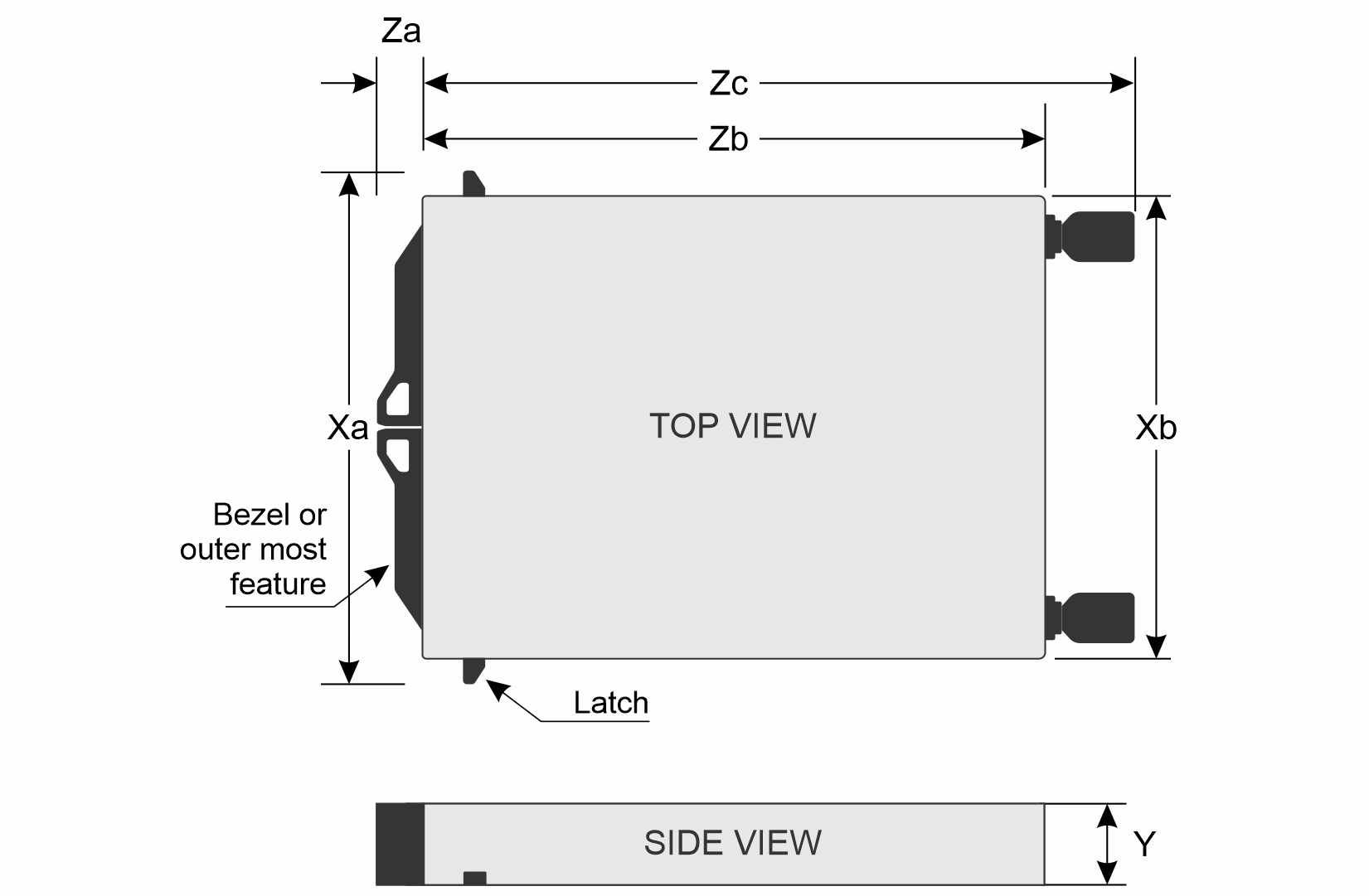
| Xa | Xb | Y | Za | Zb | Zc |
|---|---|---|---|---|---|
| 560 mm (22.05 inches) NOTE:The front bezel is not supported and no
rack ears | 537.0 mm (21.14 inches) | 46.45 mm (1.83 inches) | 71.81 mm (2.83 inch) NOTE:The front bezel
is not supported | 789.85 mm (31.10 inches)Hook to chassis rear | 848.80 mm (33.41 inches)Hook to IMM module alighment cup |
System Weight
| System Configuration | Maximum Weight (with all drives/SSDs) |
|---|---|
| 4 x16 Full height Riser configuration | 26.37 kg (58.13 lb) |
| 4 x8 Low profile + 4 x E3.S configuration | 27.9 kg (61.5 lb) |
Processor specifications
| Supported processor | Number of processors supported |
|---|---|
| 5th Generation AMD EPYC 9005 Series processor | Two per node, four per system |
DC-SCM Specifications
The new module design uses a Main + Attic board construction with high leverage from the standard design. The DC-SCM module will dock into the SCI connector on the HPM. The module is spec compliant and can be used with future DC-MHS compliant boards as well.
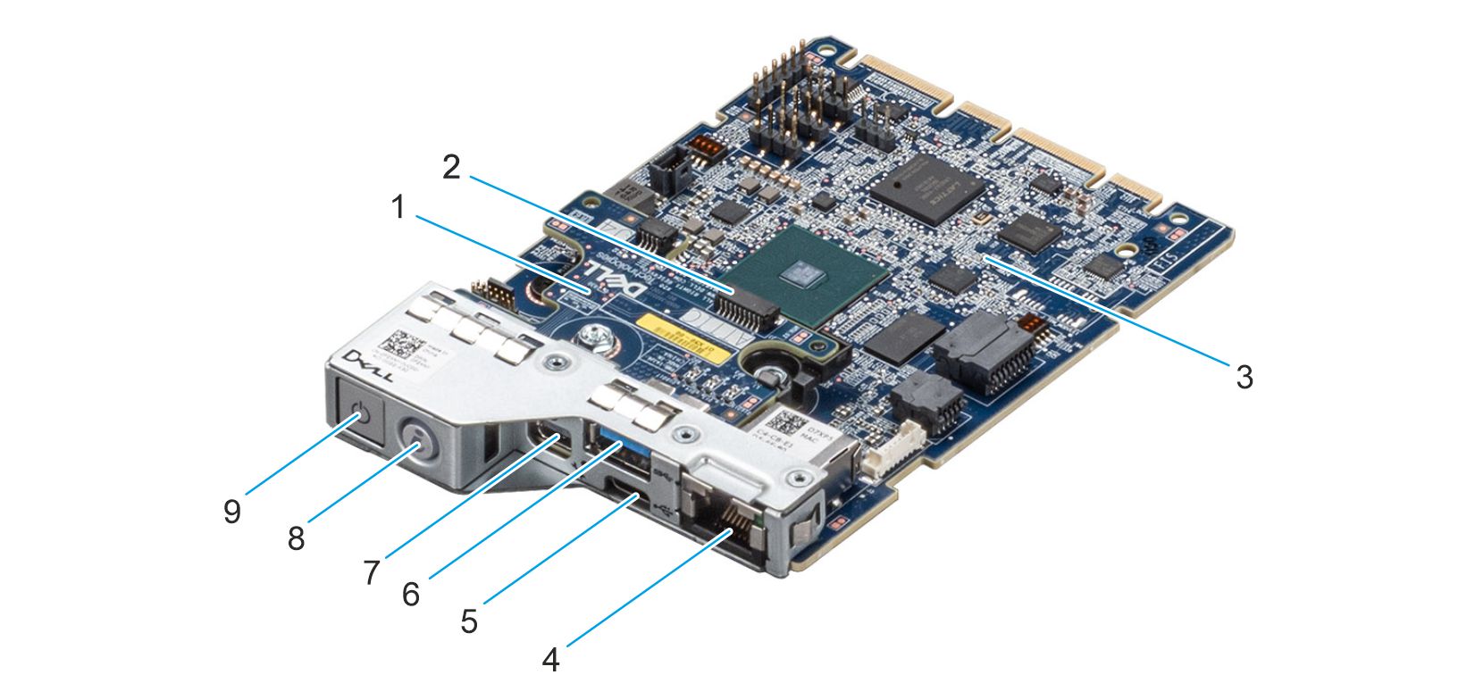
- Attic board
- rSPI cable connector
- Main board
- iDRAC10 dedicated RJ-45 GbE port
- USB Type C iDRAC direct port
- USB Type A
- Mini DisplayPort
- System ID button
- Power button
Power distribution board
Features and Layout
The PDB is designed to support both the M7725 HPMs and future 12 V HPMs. It features two independent halves, each serving one of the two compute nodes housed within the chassis. The only shared component between the two halves is the 50 V DC busbar cable entry. Each half is dedicated to powering a single compute node and includes:
- HSC (Hot Swap Control) so we can do a virtual AC cycle per node
- Two parallel power bricks for 12 V DC output at 3200 W
- One leak detect (cold plate) connector
- Two leak detect rope connectors
- 77 mm card edge gold fingers for 12 V output
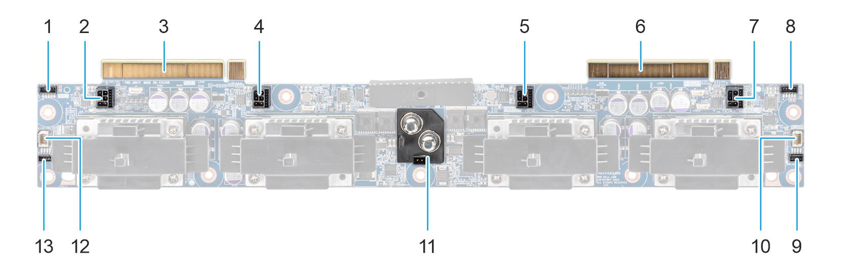
- Leak detection rope 2 connector (Node 2)
- Fan 2 connector (Node 2)
- Node 2 HPM connector
- Fan 1 connector (Node 2)
- Fan 2 connector (Node 1)
- Node 1 HPM connector
- Fan 1 connector (Node 1)
- Leak detection rope 2 connector (Node 1)
- Leak detection rope 1 connector (Node 1)
- Leak detection cable connector
- Power bus bar PDB connector
- Leak detection cable connector
- Leak detection rope 1 connector (Node 2)
Cooling fan specifications
The PowerEdgeM7725system supports up to two sets of cabled fan modules of standard (STD) cooling fans or high performance (HPR) gold cooling fans per node.
| Fan type | Abbreviation | Also known as | Label color | Label image |
|---|---|---|---|---|
| Standard (STD) fans | STD | STD | No label | 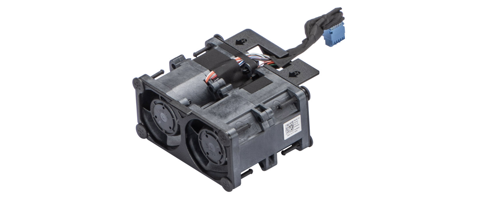 |
| High performance | HPR Gold | HPR | Gold | 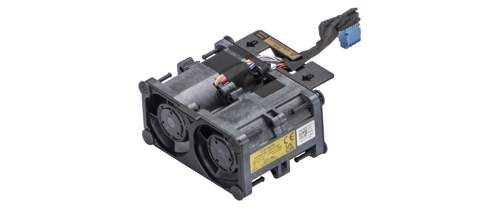 |
Supported operating systems
The Dell PowerEdge M7725 supports the following operating systems:
- Canonical Ubuntu Server LTS
- SUSE Linux Enterprise Server
- Red Hat Enterprise Linux
System battery specifications
The PowerEdge M7725 system uses one CR 2032 3.0-V lithium coin cell battery.
Expansion card riser specifications
| Config | Riser/OCP | Category | Slot | Form Factor | Slot's electrical bandwidth/ physical connector | Power | |
|---|---|---|---|---|---|---|---|
| RC0 | 1x OCP (x16) + 2x FH (x16) per node | F1B | Cabled Riser | 1 | Full Height | PCIe Gen5 x16 (x16 connector) | 75 W |
| F2B | Cabled Riser | 3 | Full Height | PCIe Gen5 x16 (x16 connector) | 75 W | ||
| OCP | Cabled Riser | 2 | OCP | PCIe Gen5 x16 (OCP 4C+ connector) | 75 W | ||
| RC1 | 1x OCP (x16) + 2x LP (x16) + 2x E3 (x4) per node | F1A | Cabled Riser | 1 | Low Profile | PCIe Gen5 x16 (x16 connector) | 75 W |
| F2A | Cabled Riser | 3 | Low Profile | PCIe Gen5 x16 (x16 connector) | 75 W | ||
| Onboard OCP | Cabled Riser | 2 | OCP | PCIe Gen5 x16 (OCP 4C+ connector) | 75 W | ||
Memory specifications
| DIMM type | DIMM rank | DIMM capacity | Minimum system capacity | Maximum system capacity |
|---|---|---|---|---|
| DDR5 ECC RDIMM | Dual rank | 32 GB | 32 GB | 768 GB |
| Dual rank | 64 GB | 64 GB | 1.5 TB | |
| Dual rank | 96 GB | 96 GB | 2.3 TB | |
| Dual rank | 128 GB | 128 GB | 3 TB |
| Memory module sockets | Speed |
|---|---|
| 24 DDR5 DIMM slots | 6400 MT/s |
Storage controller specifications
| Supported storage controller cards | |
|---|---|
Internal Boot
|
NIC port specifications
| Feature | Specifications |
|---|---|
| OCP 3.0 Card | 10 GbE x 2, 25 GbE x 2 |
USB ports specifications
| Front | Internal | ||
|---|---|---|---|
| USB port type | No. of ports | USB port type | No. of ports |
| USB 2.0-compliant port on DC-SCM | One | Internal USB 3.0-compliant port | One |
| Type-C USB 2.0-compliant port on DC-SCM | One | ||
Video ports specifications
The PowerEdge M7725 system supports one Mini-DisplayPort on DC-SCM module.
Video specifications
| Common video mode | Timing name | Pixel frequency | Refresh rate |
|---|---|---|---|
| VGA | 640 x 480 | 25.2 MHz | 60 Hz |
| SVGA | 800 x 600 | 40 MHz | 60 Hz |
| XGA | 1024x768 | 65 MHz | 60 Hz |
| WXGA | 1280x768 reduced blanking | 68.25 MHz | 60 Hz |
| HDTV | 1280 x 720 P | 74.25 MHz | 60 Hz |
| HDTV | 1280 x 720 P | 74.25 MHz | 60 Hz |
| HDTV | 1280 x 720 P | 74.25 MHz | 60 Hz |
| HDTV | 1920 x 1080i | 74.25 MHz | 60 Hz |
| HDTV | 1920 x 1080p | 74.25 MHz | 60 Hz |
| HD | 1360 x 768 | 85.5 MHz | 60 Hz |
| SXGA | 1280 x 1024 | 108 MHz | 60 Hz |
| SXGA+ | 1400 x 1050 reduced blanking | 101 MHz | 60 Hz |
| WSXGA+ | 1680 x 1050 reduced blanking | 119 MHz | 60 Hz |
| UXGA | 1600 x 1200 | 162 MHz | 60 Hz |
| FHD | 1920 x 1080 P | 148.5 MHz | 60 Hz |
| FHD | 1920 x 1080 P | 148.5 MHz | 60 Hz |
| WUXGA | 1920 x 1200 reduced blanking | 154 MHz | 60 Hz |
| QXGA | 2048 x 1536 | 266.9 MHz | 60 Hz |
| WQXGA | 2560 x 1600 reduced blanking | 268.5 MHz | 60 Hz |
Environmental specifications
| Category A2 | Allowable Operation |
|---|---|
| Temperature Ranges (For Altitude <900 meters or 2953 feet) | 10 °C–35°C (50°F – 95°F) with no direct sunlight on the platform |
| Humidity Percent Ranges (Non-Condensing at all times) | 8%RH with -12°C minimum dew point to 80%RH with 21°C (69.8°F) maximum dew point |
| Operational Altitude De-Rating | Maximum temperature is reduced by 1°C/300 meters (1.8°F/984 feet) above 900 meters (2,953 feet) |
| Allowable Operation | |
|---|---|
| Maximum Temperature Gradient (applies to both operation and non-operation) | 20°C in an hour* (36°F in an hour) and 5°C in 15 minutes (9°F in 15 minutes), 5°C in an hour* (9°F in an hour) for tape hardware |
| Non-Operational Temperature Limits | -40°(-5)** C to 65°C (-40°(23) F to 149°F |
| Non-Operational Humidity Limits (Non-Condensing at all times) | 5% to 95%RH with 27°C (80.6°F) maximum dew point. |
| Maximum Non-Operational Altitude | 12,000 meters (39,370 feet) |
| Maximum Operational Altitude | 3,048 meters (10,000 feet) |
| Maximum vibration specifications | |
|---|---|
| Operating | 0.21 Grms at 5 Hz to 500 Hz (x, y, and z axes) |
| Storage | 1.38 Grms at 7 Hz to 250 Hz for 15 min (all six sides tested) |
| Maximum shock specifications | |
|---|---|
| Operating | Six consecutively performed shock pulses in the positive and negative x, y, and z axes of 6 G for up to 11 ms |
| Storage | Six consecutively performed Long Duration Half Sine Shock pulses in the positive and negative x, y, and z axes (one pulse on each side of the system) of 35 G for up to 25 ms |
Particulate and gaseous contamination specifications
The following table defines the limitations that help avoid any equipment damage or failure from particulates and gaseous contamination. If the levels of particulates or gaseous pollution exceed the specified limitations and result in equipment damage or failure, you must rectify the environmental conditions. Remediation of environmental conditions is the responsibility of the customer.
| Particulate contamination | Specifications |
|---|---|
| Air filtration | Data center air filtration as defined by ISO Class 8 per ISO 14644-1 with a 95% upper confidence limit.
NOTE:The ISO Class 8 condition applies to data center environments only. This air filtration requirement does not apply to IT equipment designed to be used outside a data center, in environments such as an office or factory floor.
NOTE:Air entering the data center must have MERV11 or MERV13 filtration
|
| Conductive dust | Air must be free of conductive dust, zinc whiskers, or other conductive particles.
NOTE:This condition applies to data center and non-data center environments.
|
| Corrosive dust |
NOTE:This condition applies to data center and non-data center environments.
|
| Gaseous contamination | Specifications |
|---|---|
| Copper coupon corrosion rate | <300A/month per class G1 as defines by ANSI/ISA71.04-2013 |
| Silver coupon corrosion rate | <200A/month as defined by ANSI/ISA71.04-2013 |
Thermal restriction matrix
| Label | Description |
|---|---|
| HPR GOLD | High performance Gold (HPR Gold) fan |
| LP | Low profile |
| FH | Full height |
| DLC | Direct Liquid Cooling |
| Configurations | DPU | CPU | DIMM | Fan type | DIMM blank | Air Shroud | LP/FH PCIe Filler | Fan quantities |
|---|---|---|---|---|---|---|---|---|
| SM Config | TDP | Capacity | ||||||
| Full height configuration | Yes | All TDP | All capacities | HPR Gold Fan | Required for all empty DIMM slots | Required for all configs | Required for all empty PCIe slots | 4x fan modules and 8x fans for all configs |
| No | TDP <= 400 W | DIMM <64G | VHP Fan | |||||
| DIMM = >64G | HPR Gold Fan | |||||||
| TDP > 400 W | DIMM < 64G | HPR Gold Fan | ||||||
| DIMM = >64G | HPR Gold Fan | |||||||
| Low profile +E3.S configuration | N/A | TDP <= 400 W | DIMM < 64G | VHP Fan | ||||
| DIMM = >64G | HPR Gold Fan | |||||||
| TDP > 400 W | DIMM < 64G | HPR Gold Fan | ||||||
| DIMM = > 64G | HPR Gold Fan |
| M7725 | ||||||||
|---|---|---|---|---|---|---|---|---|
| PPCM Config | Full height configuration | Low profile + E3.S configurationN/A | ||||||
| DPU | With DPU | Without DPU | ||||||
| DIMM | All capacities | < 64 GB | 64 GB <= DIMM <=128 GB | *256 GB | ||||
| M7725 | 320 W | HPR Gold fan | STD fan | HPR Gold fan | HPR Gold fan | STD fan | HPR Gold fan | HPR Gold fan |
| 360 W | HPR Gold fan | STD fan | HPR Gold fan | HPR Gold fan | STD fan | HPR Gold fan | HPR Gold fan | |
| 400 W | HPR Gold fan | STD fan | HPR Gold fan | HPR Gold fan | STD fan | HPR Gold fan | HPR Gold fan | |
| 500 W | HPR Gold fan | HPR Gold fan | HPR Gold fan | HPR Gold fan | HPR Gold fan | HPR Gold fan | HPR Gold fan | |
| Dell PowerEdge server standard operating support (ASHRAE A2 compliant) All options supported unless otherwise noted | Dell PowerEdge server extended Inletient 40°C Operating Support (ASHRAE A3 compliant) | Dell PowerEdge server extended Inletient 45°C Operating Support (ASHRAE A4 compliant) |
|---|---|---|
|
Not supported | Not supported |
| Dell PowerEdge server standard operating support (ASHRAE A2 compliant) All options supported unless otherwise noted | Dell PowerEdge server extended Inletient 40°C Operating Support (ASHRAE A3 compliant) | Dell PowerEdge server extended Inletient 45°C Operating Support (ASHRAE A4 compliant) |
|---|---|---|
|
Not supported | Not supported |