




























Population rules
| Category | Maximum population |
|---|---|
| Blanks | All the empty slots in the MX7000 enclosure must be populated with blanks (Sled, IOM, EC, and PSU). This is required for proper cooling of the enclosure and components. |
| Fans | All system fans must be populated in the enclosure. Do not to mix Gen 1 (silver grade) fan and Gen 2 (gold grade) fan in the same chassis. |
| Power supply units | The number of power supply units that are required is dependent upon system configuration and redundancy mode, and the minimum recommended quantity is two. The six PSUs are organized into two groups: Grid A consists of PSUs 1, 2, 3, and Grid B consists of PSUs 4, 5, 6. It is recommended to populate the PSUs in the following order: 1, 4, 2, 5, 3, 6 where an equal number of PSUs on each grid is optimized for Grid Redundancy. PSU redundancy and No Redundancy options do not have any PSU population requirements. |
| Power cable | AC: One C21/C20 power cable must be connected to the C22 plug corresponding to each populated PSU. |
| DC power and ground cables | The DC chassis requires special consideration when attaching to site power. Power and ground cables must both use 2AWG wire.
NOTE:For information about the DC PSU cabling instructions, please see the Cabling instructions for -48 V to -60 V DC power supply Tech sheet that is shipped together with your DC PSU.
|
| Management module | A Management module must be present to control and manage the enclosure.
NOTE:If a single Management module crashes, the system functions normally.
NOTE:The enclosure cannot be managed or controlled until the Management module is replaced.
|
| Control panel | The right control panel and one of the left control panel configurations (LCD or LED) must be present on the MX7000 enclosure. |
| Compute sled | Up to eight single-width or four double-width sleds or a combination can be populated. The double-width sleds must be in slots 1, 3, 5, 7 due to the enclosures design. |
| Storage Sled |
Up to seven Storage sleds can be populated in the enclosure. NOTE:One compute node must be present and it must be mapped to a storage node.
One Fabric-C SAS IOM must be present and powered ON.
|
| I/O Module | Only Brocade and SAS IOM are supported in Fabric-C. |
| Only one type of IOM can be offered in Fabric-C (Fibre Channel or SAS IOM, not mixed). | |
| Only one type of switch can be offered in Fabric-B (HPCC or Ethernet). | |
| Two Fabric-C SAS IOMs must be installed if the enclosure contains a Storage Node. | |
| Mix Speed of pass-through in same fabric is not enabled. | |
| Mezzanine cards | If the enclosure contains a storage node, Fabric-C MiniMezzanine card (HBA330 or Jumbo PERC) must be installed in one compute node. |
| Dual Port or quad port mezzanine cards must be installed for redundant IOM/Pass-through configurations. | |
| The second processor must be installed on the compute node to support Fabric-B Mezzanine / IOM and Fabric-C Mezzanine / IOM. |
MX Infrastructure Thermal Management feature for MX760c sleds tech sheet
MX760c configurations that require a thermally optimized chassis will have a specific component on the order.
| Component | description |
|---|---|
| SKU 389-EEXH | High Performance Component |
| MOD MDW67 | MOD, INFO, HIGH PERFORM COMPONENT |
- MX7000 Gold Grade (Hardware version 2, Gen2) fans (customer kit PN: H2YC5/SKU: SKU 750-ADWN; included in MX solutions orders with MX760c)
- OME-M (OpenManage Enterprise - Modular) FW 2.00.00.
(scan the QR code to download the firmware)

- iDRAC FW 05.10.25/06.10.05
(scan the QR code to download the drivers on sleds installed in MX7000 chassis)

- Enterprise Infrastructure Planning Tool (EIPT)
(scan the QR code to access the EIPT)

To setup the sled:
- Power off the MX7000 chassis.
- Install the eight, MX760c sleds at the front of the enclosure.
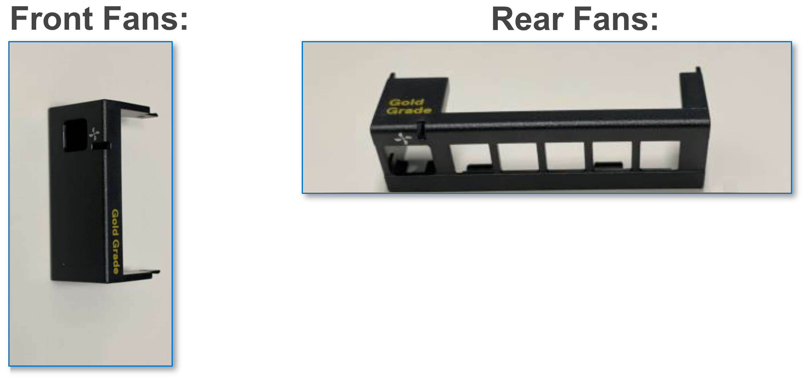
- Install the four, 60 mm gold grade (Gen 2) fans at the front and the five, 80 mm gold grade (Gen 2) fans at the rear of the MX7000 chassis.
- To verify if correct gold grade fans are installed, use one of the following methods:
Physical Verification:
- Identify the Gold Grade silksreen on the fan module
Remote verification via OME-M API:
- Open a browser and type this URL - https://<your chassis management IP>/api/DeviceService/ Devices
- Press Ctrl+F to find the first instance of "ChassisId"
- Replace the Devices number in this URL: https://<your chassis management IP>/api/DeviceService/ Devices(<ChassisId>)/InventoryDetails('chassisFansList') and press Enter to view the fan hardware version.
Remote verification via OME-M GUI:
- Click MM GUI >Hardware > Fans
- Results Gold Grade fans are shown under Hardware Version as 2.
- Results Silver Grade fans are shown under Hardware Version as 1.
PSU redundancy and population rules
- No redundancy: This mode distributes the enclosure power load across all PSUs. There are no specific PSU population requirements for No redundancy. The intent of this mode is to have the highest possible limit for power enablement of devices that are added to the enclosure. If there are single or multiple PSU failures, then the enclosure limits performance to operate within the power capabilities of the remaining PSUs.
- Grid redundancy: This mode distributes the enclosure power load across all PSUs. The six PSUs are organized into two groups: Grid A consisting of PSUs 1, 2, 3, and Grid B consists of PSUs 4, 5, 6. For grid redundancy, PSUs should be populated in the following order: 1, 4, 2, 5, 3, 6. The grid with the largest PSU capacity determines the limit for power enablement of devices that are added to the enclosure. If there is a grid or PSU failure, then the enclosure power is distributed among the remaining PSUs with the intent that a single healthy grid will continue to provide power to all the components in the system which can experience varied performance depending on the workload.
- PSU redundancy: This mode distributes the enclosure power load across all PSUs. There are no specific PSU population requirements for PSU redundancy. PSU redundancy is optimized for a population of six PSUs, and the enclosure limits the power enablement of devices to fit within five PSUs. If there is a single PSU failure, then the enclosure power is distributed among the remaining PSUs to provide power to all the components in the system which can experience varied performance depending on the workload. If there are fewer than six PSUs, then the enclosure limits the power enablement of devices to fit within all populated PSUs. If there is a single PSU failure, then the enclosure limits performance to operate within the power capabilities of the remaining PSUs.
| PSU count | Population order |
|---|---|
| 2 | 1, 4 (Optimized for Grid Redundancy 1+1, and Hot Spare) |
| 3 | 1, 4, 2 |
| 4 | 1, 4, 2, 5 (Optimized for Grid Redundancy 2+2, and Hot Spare) |
| 5 | 1, 4, 2, 5, 3 |
| 6 | 1, 4, 2, 5, 3, 6 (Optimized for Grid Redundancy 3+3, PSU Redundancy 5+1, and Hot Spare) |
Hot Spare: The MX7000 PSUs support the Hot Spare feature with three PSU pairs. This feature enables a PSU pair to have one active PSU and one PSU in sleep mode while the enclosure power consumption is low, and the three PSU pairs meet all the power requirements for the enclosure. This enables efficient power utilization when the overall enclosure power requirement is low. The partner PSU wakes the paired PSU from sleep mode by sending a WAKE signal when the enclosure power requirement increases. The PSU pairs for MX7000 are—1 & 4, 2 & 5, and 3 & 6.
Chassis dimensions
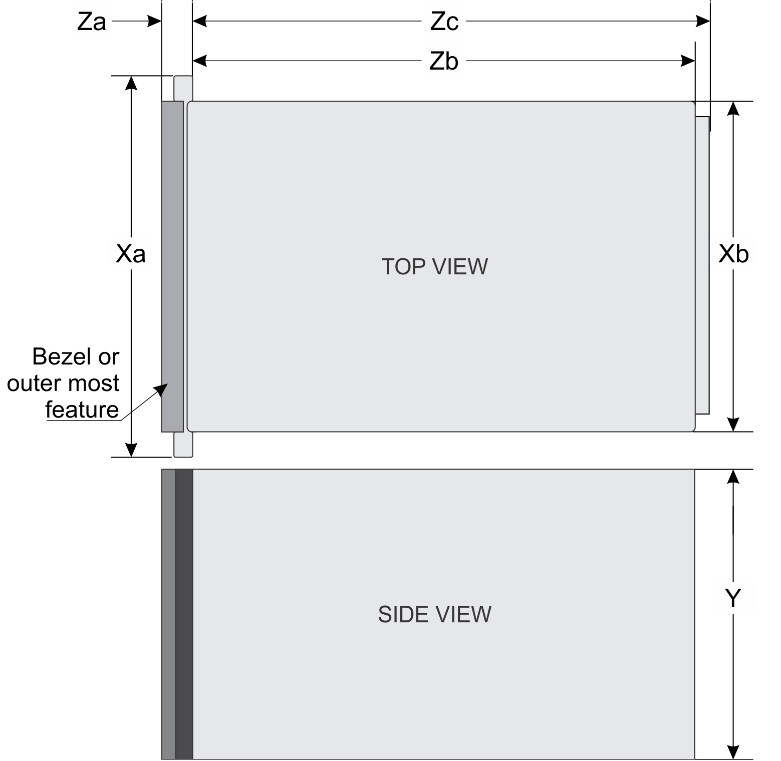
| Description | Dimension |
|---|---|
| Xa | 482 mm (18.98 inches) |
| Xb | 445 mm (17.52 inches) |
| Y | 307.4 mm (12.11 inches) |
| Zb | 811.6 mm (31.96 inches) |
| Zc | 816.6 mm (32.15 inches) |
Chassis weight
| Enclosure | Minimum weight | Maximum weight (fully populated) |
|---|---|---|
| PowerEdge MX7000 | 82 kg (180 lb) | 182 kg (400 lb) |
Fan specifications
The PowerEdge MX7000 enclosure supports four front accessible hot-swap cooling fans and five rear accessible hot-swap cooling fans (Gen 2 fans are required). The cooling fan assembly ensures that the key components of the server such as the sleds, Fabrics, and I/O modules get adequate air circulation to keep them cool. A cooling fan failure can result in overheating and may lead to damage.
| Fan location | Front | Rear |
|---|---|---|
| Size | 60 mm | 80 mm |
| Number of fans | 4 | 5 |
| Redundancy | 3+1 | 4+1 |
PSU specifications
| Description | Specification |
|---|---|
| PSU | 6 x 3000 W AC |
| Class | Platinum |
| Heat dissipation (maximum) | 1205 BTU/hr |
| Frequency | 50/60 Hz |
| Voltage | 100–240 V AC, autoranging |
| Current | 6 x 16 A for AC input
6 x 83.2 A for DC input |
| Inrush current (AC) |
|
| Connector | AC connector |
USB ports
Mini DisplayPort
The PowerEdge MX7000 enclosure supports one Mini DisplayPort (mini DP) on the front panel.
PowerEdge MX modules ports and connectors
PowerEdge MX760c
| Connector | Description |
|---|---|
| USB ports |
NOTE:The micro USB 2.0-compliant port on the front of the sled can only be used as an iDRAC Direct port.
|
PowerEdge MX750c
| Connector | Description |
|---|---|
| USB ports |
NOTE:The micro USB 2.0-compliant port on the front of the sled can only be used as an iDRAC Direct port.
|
PowerEdge MX740c
| Connector | Description |
|---|---|
| USB ports |
NOTE:The micro USB 2.0-compliant port on the front of the sled can
only be used as an iDRAC Direct port.
|
PowerEdge MX840c
| Connector | Description |
|---|---|
| USB ports |
NOTE:The micro USB 2.0-compliant port on the front of the sled can
only be used as an iDRAC Direct port.
|
MX7116n Fabric Expander Module
| Connector | Description |
|---|---|
| Externally accessible connectors |
|
MX9116n Fabric Switching Engine
| Connector | Description |
|---|---|
| Externally accessible connectors |
|
MX9002m Management Module
| Connector | Description |
|---|---|
| Externally accessible connectors |
|
MX5108n Ethernet Switch
| Connector | Description |
|---|---|
| Externally accessible connectors |
|
MXG610s Fibre Channel Switch
| Connector | Description |
|---|---|
| USB port | One micro USB 2.0-compliant port on the front of the sled. |
| Fibre Channel transceiver | 16 external ports supporting 8/ 16/ 32 Gbps speeds using 8 SFPs and 2 QSFPs. |
PowerEdge MX 10GBASE-T Ethernet Pass-Through Module
| Connector | Description |
|---|---|
| Fibre Channel transceiver | 16 external ports supporting 10 GbE connections |
PowerEdge MX 25 Gb Ethernet Pass-Through Module
| Connector | Description |
|---|---|
| Fibre Channel transceiver | 16 external ports supporting 25 GbE connections |
Video specifications
| Resolution | Refresh rate Hz | Color depth (bits) |
|---|---|---|
| 1024 x 768 | 60 | 8, 16, 32 |
| 1280 x 800 | 60 | 8, 16, 32 |
| 1280 x 1024 | 60 | 8, 16, 32 |
| 1360 x 768 | 60 | 8, 16, 32 |
| 1440 x 900 | 60 | 8, 16, 32 |
| 1600 x 900 | 60 | 8, 16, 32 |
| 1600 x 1200 | 60 | 8, 16, 32 |
| 1680 x 1050 | 60 | 8, 16, 32 |
| 1920 x 1080 | 60 | 8, 16, 32 |
| 1920 x 1200 | 60 | 8, 16, 32 |
Environmental specifications
| Temperature | Specifications |
|---|---|
| Storage | –40°C to 65°C (–40°F to 149°F) |
Maximum temperature gradient |
20°C/h (36°F/h) |
| Relative humidity | Specifications |
|---|---|
| Storage | 5% to 95% RH with 33°C (91°F) maximum dew point. Atmosphere must be noncondensing always. |
| Operating | 10% to 80% RH with 29°C (84.2°F) maximum dew point. |
| Maximum vibration | Specifications |
|---|---|
| Operating | 0.26 Grms at 5 Hz to 350 Hz (all axis) |
| Storage | 1.88 Grms at 10 Hz to 500 Hz (vertical axis) |
| Maximum shock pulse | Specifications |
|---|---|
| Operating | Shock pulses in the positive and negative x, y, and z axis of 6 G for up to 11 ms. |
| Storage | Shock pulses in the positive z axis of 71 G for up to 2 ms. |
| Maximum altitude | Specifications |
|---|---|
| Operating | 3048 m (10,000 ft) |
| Storage | 12,000 m (39,370 ft) |
| Operating temperature derating | Specifications |
|---|---|
| Up to 35°C (95°F) | Maximum temperature reduces by 1°C/300 m (1°F/547 ft), above 950 m (3,117 ft). |
| 35°C to 40°C (95°F to 104°F) | Maximum temperature reduces by 1°C/175 m (1°F/319 ft), above 950 m (3,117 ft). |
| 40°C to 45°C (104°F to 113°F) | Maximum temperature reduces by 1°C/125 m (1°F/228 ft), above 950 m (3,117 ft). |
Standard operating temperature
| Standard operating temperature | Specifications |
|---|---|
Continuous operation |
10°C to 35°C (50°F to 95°F) |
Expanded operating temperature
| Expanded operating temperature | Specifications |
|---|---|
| Continuous operation | 5°C to 40°C at 5% to 85% RH with 29°C dew point. NOTE:Outside the standard
operating temperature (10°C to 35°C), the system can operate continuously
in temperatures as low as 5°C and as high as 40°C. For temperatures 35°C to 40°C, derate maximum allowable temperature by 1°C per 175 m (1°F per 319 ft) above 950 m (3,1171 ft). |
| ≤ 1% of annual operating hours | –5°C to 45°C at 5% to 90% RH with 29°C dew point. NOTE:Outside the standard
operating temperature (10°C–35°C), the system can operate down
to –5°C or up to 45°C for a maximum of 1% of its annual operating
hours. For temperatures between 40°C and 45°C, derate maximum allowable temperature by 1°C per 125 m (1°F per 228 ft) above 950 m (3.117 ft). |
Expanded operating range
- The operating temperature is specified for a maximum altitude of 950 m for expanded operating range.
- Do not perform cold start at 5°C or lower, due to hard drive constraints.
- Redundant power supplies are required.
Expanded operating temperature restrictions
For more information about the expanded operating temperature restrictions, see the Installation and Service Manual for the PowerEdge MX sleds at PowerEdge manuals.
| System | C30 | C35 | C40E45 |
|---|---|---|---|
| Dell PowerEdge MX7000 including the fans, Management Module, and PSUs | No restrictions | No restrictions | No restrictions |
| Fabrics A and B modules | No restrictions | No restrictions | The MX9116n is not supported. |
| Fabric C I/O modules | No restrictions | No restrictions | No restrictions |
Particulate and gaseous contamination specifications
| Particulate contamination | Specifications |
|---|---|
| Air Filtration | Data center air filtration defines that, ISO Class 8 per ISO 14644-1 with a 95% upper confidence limit. NOTE:This condition
applies to data center environments only. Air filtration requirements
do not apply to IT equipment designed to be used outside a data center,
in environments such as an office or factory floor. NOTE:Air entering the data
center must have MERV11 or MERV13 filtration. |
Conductive dust |
Air must be free of conductive dust, zinc whiskers, or other conductive particles. NOTE:This condition applies
to data center and nondata center environments. |
Corrosive dust |
NOTE:This condition
applies to data center and nondata center environments. |
| Gaseous contamination | Specifications |
|---|---|
| Copper Coupon Corrosion | <300 Å/month per Class G1 defines that, ANSI/ISA71.04-1985. |
| Silver Coupon Corrosion | <200 Å/month defines that, AHSRAE TC9.9. |