




























Сегодня покупают
← Вернуться назад
Нужна помощь с конфигурацией?
Пришлите SKU, спецификацию или список требований. Специалист Apltech проверит совместимость компонентов и найдёт актуальные артикулы
Получить консультацию →

Dell EMC PowerEdge MX5016s and MX5000s: технические характеристики и спецификации

Sled dimensions

Table 1. System dimensions of the Dell EMC PowerEdge MX5016s . System dimensions
System Height Width Depth(handle closed)
PowerEdge MX5016s 250.2 mm (9.85 inches) 42.15 mm (1.65 inches) 600.00 mm (23.62 inches)

Sled weight

Table 1. Dell EMC PowerEdge MX5016s system weight . Dell EMC PowerEdge MX5016s system weight
System Maximum weight
PowerEdgeMX5016s 12 kg (26.45 lbs)

Supported operating systems

The Dell EMC PowerEdge MX5016s supports the following operating systems:

Red Hat Enterprise Linux Novell SUSE Linux Enterprise Server Microsoft Windows Server Ubuntu VMware ESXi Citrix Xen Server

For more information about the specific versions and additions, go to https://www.dell.com/support/home/us/en/04/Drivers/SupportedOS/poweredge-MX5016s

Storage expander specifications

The storage expander modules provide the storage subsystem for the drives in the PowerEdge MX5016s. The SAS expanders each connect to ports on all 16 HDDs. The first expander connects to port A of the first eight HDDs and port B of the second eight HDDs. The second expander is the opposite and connects to port B of the first eight HDDs and port A of the other eight HDDs. There is also a SAS link between the expanders to facilitate communication/synchronization between the two expanders.

Drive specifications

The Dell EMC PowerEdge MX5016s supports the following drive types:

  • Support for 10,000 RPM and 15,000 RPM 2.5-inch SAS drives
  • Support for 2.5-inch SAS SSD
  • Support for 7.2 K RPM 2.5-inch NearLine SAS drives
  • NOTE: SATA and NVMe drives are not supported but mixing of rotational and SSD SAS drives is supported.

Drive assignment

Each slot in the PowerEdge MX7000 chassis supports a Compute Sled or a Storage Sled, and there are no fixed mappings for the sleds. Using the OpenManage Enterprise-Modular web interface the disks in a storage sled can be mapped to a Compute Sled that gives you the following options:
  • Enclosure-Assigned mode
  • Drive-Assigned mode
Enclosure-Assigned mode:
  • All the drives in the PowerEdge MX5016s are assigned to the selected compute sleds.
  • The Fab-C Mezz controller can be either PERC H745P MX, or HBA330 MMZ. Enclosure assignment mode is required if the PowerEdge MX5016s is to be shared between multiple compute sleds (that is clustered). Only HBA330 MMZ controller supports shared assignments.
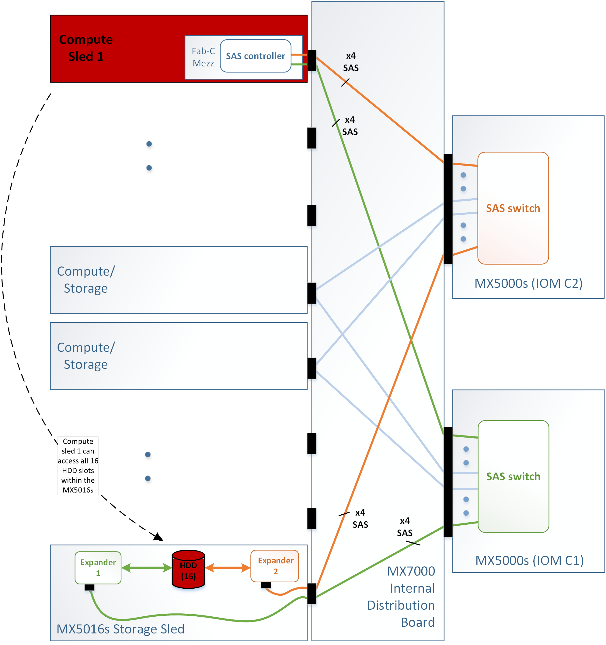
Figure 1. Enclosure-Assigned modeThis image shows Enclosure-Assigned mode.
Drive-Assigned mode:
  • A specified group of disks is assigned.
  • Drive-Assigned mode assigns the individual drive from the PowerEdge MX5016s to another compute sleds (but cannot be assigned to more than one sled simultaneously). The Fab-C Mezz controller on the mapped compute sled can be either a PERC H745P MX, or HBA330 MMZ.
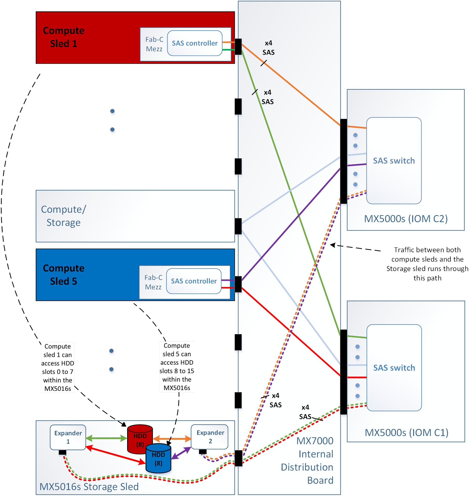
Figure 2. Drive-Assigned modeThis image shows Drive-Assigned mode.

The first compute sled maps to disks 0 through 7 and the other compute sled maps to disks 8 through 15. The disk assignment can be asymmetric, for example, 12 drives that are mapped to the first compute sled and 4 drives to the other compute sled. Also the disks can be divided up among more than two compute sleds, for example, four disks to each of 4 compute sleds.

Module dimensions

Table 1. Dimensions of the Dell EMC PowerEdge MX5000s . Dell EMC PowerEdge MX5000s dimensions
System Height Width Depth(handle closed)
PowerEdge MX5000s 27.50 mm (1.08 inches) 214.50 mm (8.44 inches) 208.30 mm (8.20 inches)

Module weight

Table 1. Dell EMC PowerEdge MX5000s module weight . Dell EMC PowerEdge MX5000s module weight
System Maximum weight
PowerEdge MX5000s 1.5 kg (3.30 lb)

Environmental specifications

  • NOTE: For additional information about environmental measurements for specific system configurations, see Dell.com/environmental_datasheets.
Table 1. Temperature specifications . When the system is in continuous operation (for altitude less than 950 m or 3117 ft), the temperature specification ranges from 10°C to 35°C (50°F to 95°F) with no direct sunlight on the equipment. NOTE: Maximum of 145 W 22 core processor is supported in systems with eight 2.5-inches drives, two PCI slot chassis, and 75 W single wide active GPU. When the system is not in operation, the temperature specification is –40°C to 65°C (–40°F to 149°F). The Maximum temperature gradient for both opertaion and non-opertaional systems is 20°C/h (36°F/h).
Temperature Specifications
Storage –40°C to 65°C (–40°F to 149°F)
Continuous operation (for altitude less than 950 m or 3117 ft) 10°C to 35°C (50°F to 95°F) with no direct sunlight on the equipment.
Maximum temperature gradient (operating and storage) 20°C/h (68°F/h)
Table 2. Relative humidity specifications . For a non-operational system, the ambient relative humidity ranges from 5% to 95% with 33°C (91°F) maximum dew point. Atmosphere must be non-condensing at all times. For an operational system, the ambient relative humidity ranges from 10% to 80% with 29°C (84.2°F) maximum dew point.
Relative humidity Specifications
Storage 5% to 95% RH with 33°C (91°F) maximum dew point. Atmosphere must be non-condensing at all times.
Operating 10% to 80% relative humidity with 26°C (78.8°F) maximum dew point.
Table 3. Maximum vibration specifications . The maximum vibration specification of an operational system is 0.26 Grms at 5 Hz to 350 Hz (all operation orientations).The maximum vibration specification of a non-operational system is 1.87 Grms at 10 Hz to 500 Hz for 15 min (all six sides tested).
Maximum vibration Specifications
Operating 0.26 G rms at 5 Hz to 350 Hz (all operation orientations).
Storage 1.87 G rms at 10 Hz to 500 Hz for 15 min (all six sides tested).
Table 4. Maximum shock specifications . The maximum shock specification of an operational system is six consecutively executed shock pulses in the positive and negative x, y, and z axes of 6 G for up to 11 ms. The maximum shock specification of a non-operational system is six consecutively executed shock pulses in the positive and negative x, y, and z axes (one pulse on each side of the system) of 71 G for up to 2 ms.
Maximum shock Specifications
Operating One shock pulse in the positive z axis of 31 G for 2.6 ms in the operational orientation.
Storage Six consecutively executed shock pulses in the positive and negative x, y, and z axes (one pulse on each side of the system) of 71 G for up to 2 ms.
Table 5. Maximum altitude specifications . The maximum altitude specification for an operational system is 3048 m (10,000 ft). The maximum altitude specification for a non-operational system is 12,000 m (39,370 ft).
Maximum altitude Specifications
Operating

3048 m ( 10,000 ft)

Storage 12,000 m (39,370 ft)
Table 6. Operating temperature de-rating specifications . If the operating temerature of a system is up to 35 °C (95 °F), the maximum temperature is reduced by 1 °C/300 m (1 °F/547 ft) above 950 m (3,117 ft). If the operating temperature of a system ranges from 35 °C to 40 °C (95 °F to 104 °F), the maximum temperature is reduced by 1 °C/175 m (1 °F/319 ft) above 950 m (3,117 ft). If the operating temperature of a system ranges from 40 °C to 45 °C (104 °F to 113 °F), the maximum temperature is reduced by 1 °C/125 m (1 °F/228 ft) above 950 m (3,117 ft).
Operating temperature de-rating Specifications
Up to 35°C (95°F) Maximum temperature is reduced by 1°C/300 m (1°F/547 ft) above 950 m (3,117 ft).
35°C to 40°C (95°F to 104°F) Maximum temperature is reduced by 1°C/175 m (1°F/319 ft) above 950 m (3,117 ft).
40°C to 45°C (104°F to 113°F) Maximum temperature is reduced by 1°C/125 m (1°F/228 ft) above 950 m (3,117 ft).

Expanded operating temperature

Table 1. Expanded operating temperature specifications . When the system is in continuous operation, the expanded operating temperature ranges from 5°C to 40°C at 5% to 85% RH with 29°C dew point. NOTE: Outside the standard operating temperature (10°C to 35°C), the system can operate continuously in temperatures as low as 5°C and as high as 40°C. For temperatures between 35°C and 40°C, de-rate maximum allowable dry bulb temperature by 1°C per 175 m above 950 m (1°F per 319 ft). When the system is operating at < 1% of annual operating hours, the expanded operating temperature is –5°C to 45°C at 5% to 90% RH with 29°C dew point. NOTE: Outside the standard operating temperature (10°C to 35°C), the system can operate down to –5°C or up to 45°C for a maximum of 1% of its annual operating hours. For temperatures between 40°C and 45°C, de-rate maximum allowable temperature by 1°C per 125 m above 950 m (1°F per 228 ft).
Expanded operating temperature Specifications
Less than or equal to 10% of annual operating hours 5°C to 40°C at 5% to 85% RH with 29°C dew point.
  • NOTE: Outside the standard operating temperature (10°C to 35°C), the system can operate continuously in temperatures as low as 5°C and as high as 40°C.

For temperatures between 35°C and 40°C, de-rate maximum allowable dry bulb temperature by 1°C per 175 m above 950 m (1°F per 319 ft).

Less than or equal to 1% of annual operating hours –5°C to 45°C at 5% to 90% RH with 29°C dew point.
  • NOTE: Outside the standard operating temperature (10°C to 35°C), the system can operate down to –5°C or up to 45°C for a maximum of 1% of its annual operating hours.

For temperatures between 40°C and 45°C, de-rate maximum allowable temperature by 1°C per 125 m above 950 m (1°F per 228 ft).

  • NOTE: When operating in the expanded temperature range, system performance may be impacted.
  • NOTE: When operating in the expanded temperature range, ambient temperature warnings maybe reported on the LCD panel and in the System Event Log.

Particulate and gaseous contamination specifications

The following table defines the limitations that help avoid any equipment damage or failure from particulates and gaseous contamination. If the levels of particulates or gaseous pollution exceed the specified limitations and result in equipment damage or failure, you may need to rectify the environmental conditions. Re-mediation of environmental conditions is the responsibility of the customer.
Table 1. Particulate contamination specifications . Air filtration specification: Data center air filtration as defined by ISO Class 8 per ISO 14644-1 shpuld have a 95% upper confidence limit. Note: This condition applies only to data center environments. Air filtration requirements do not apply to IT equipment designed to be used outside a data center, in environments such as an office or factory floor. Note: Air entering the data center must have MERV11 or MERV13 filtration. Conductive dust specification: Air must be free of conductive dust, zinc whiskers, or other conductive particles. Note: This condition applies to data center and non-data center environments. Corrosive dust specification: Air must be free of corrosive dust. Residual dust present in the air must have a deliquescent point less than 60% relative humidity. Note: This condition applies to data center and non-data center environments.
Particulate contamination Specifications
Air filtration Data center air filtration as defined by ISO Class 8 per ISO 14644-1 with a 95% upper confidence limit.
  • NOTE: This condition applies to data center environments only. Air filtration requirements do not apply to IT equipment designed to be used outside a data center, in environments such as an office or factory floor.
  • NOTE: Air entering the data center must have MERV11 or MERV13 filtration.
Conductive dust Air must be free of conductive dust, zinc whiskers, or other conductive particles.
  • NOTE: This condition applies to data center and non-data center environments.
Corrosive dust
  • Air must be free of corrosive dust.
  • Residual dust present in the air must have a deliquescent point less than 60% relative humidity.
  • NOTE: This condition applies to data center and non-data center environments.
Table 2. Gaseous contamination specifications . The copper coupon corrosion rate is <300 Å/month per Class G1 as defined by ANSI/ISA71.04-1985. The silver coupon corrosion rate is <200 Å/month as defined by AHSRAE TC9.9.
Gaseous contamination Specifications
Copper coupon corrosion rate <300 Å/month per Class G1 as defined by ANSI/ISA71.04-1985.
Silver coupon corrosion rate <200 Å/month as defined by AHSRAE TC9.9.
  • NOTE: Maximum corrosive contaminant levels measured at ≤50% relative humidity.