




























Dimensions of the Dell EMCPowerEdgeC6400 enclosure
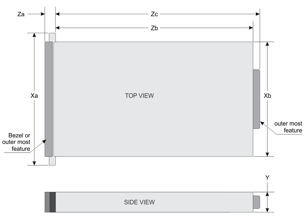
| Xa | Xb | Y | Za | Zb | Zc |
|---|---|---|---|---|---|
| 482.6 mm (19 inches) | 448 mm (17.63 inches) | 86.8 mm (3.41 inches) | 26.8 mm (1.05 inches) | 763.2 mm (30.28 inches) | 797.3 mm (31.38 inches) |
Chassis weight
| System | Maximum weight (with all sleds and drives) |
|---|---|
| 12 x 3.5-inch hard drive systems | 43.62 Kg (96.16 lb) |
| 24 x 2.5-inch hard drive systems | 41.46 Kg (91.40 lb) |
| No backplane systems | 34.56 Kg (76.19 lb) |
Supported operating systems
- Canonical Ubuntu LTS
- Citrix XenServer
- Microsoft Windows Server with Hyper-V
- Red Hat Enterprise Linux
- SUSE Linux Enterprise Server
- VMware ESXi
PSU specifications
The Dell EMC PowerEdge C6400 enclosure supports two AC power supply units (PSUs).
| PSU wattage | Class | Heat dissipation (maximum) | Frequency | Voltage | Maximum input current |
|---|---|---|---|---|---|
2400 W AC |
Platinum | 9000 BTU/hr |
50/60 Hz |
100–240 V AC, autoranging |
14 A–16 A |
2000 W AC |
Platinum | 7500 BTU/hr |
50/60 Hz |
100–240 V AC, autoranging |
11.5 A |
1600 W AC |
Platinum | 6000 BTU/hr |
50/60 Hz |
100–240 V AC, autoranging |
10 A |
Chassis management board specifications
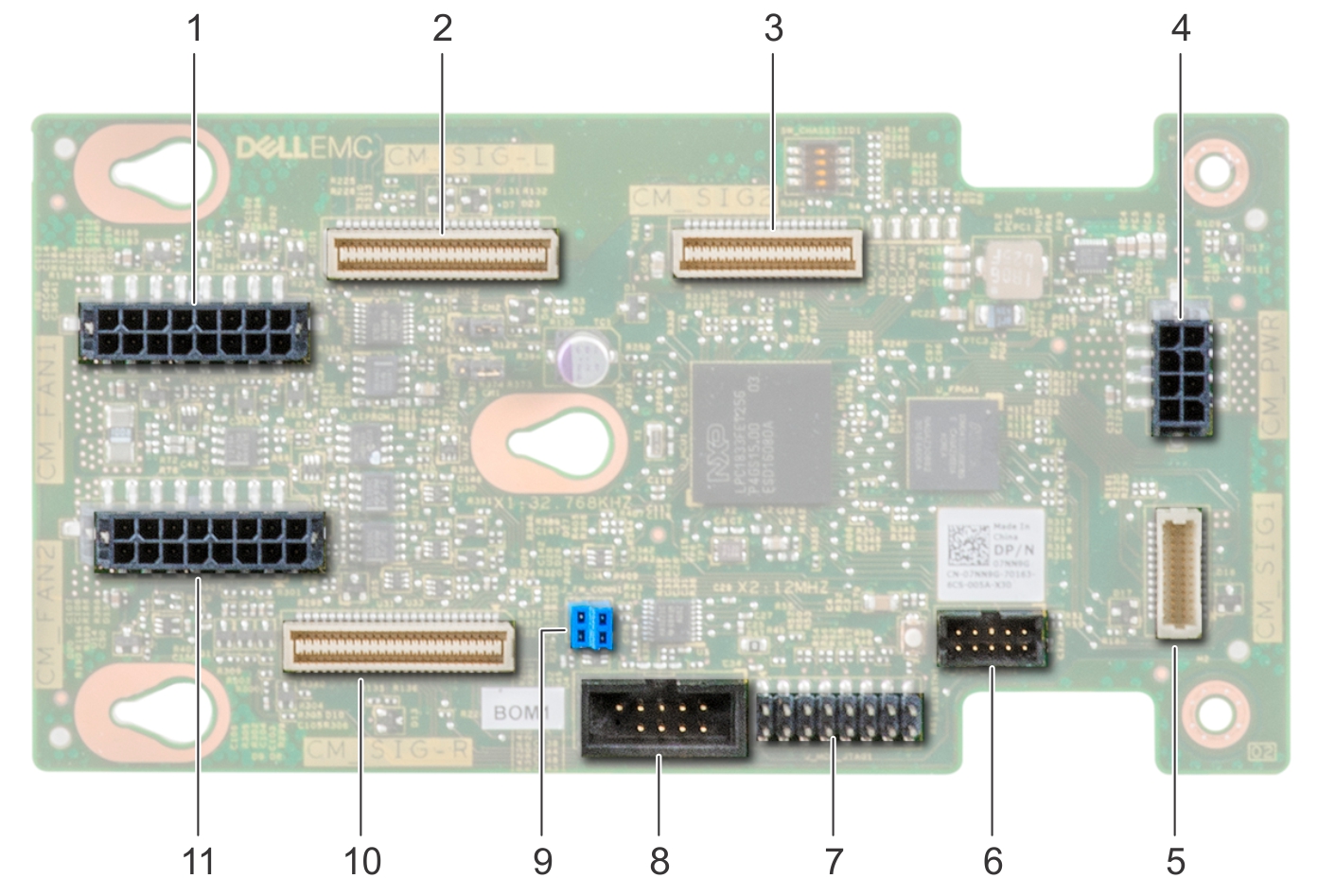
- Fan cage 1 connector for fans 1 and 2
- Left midplane signal cable
- Chassis management board signal cable to backplane
- Chassis management board power connector from PIB
- Chassis management board signal cable to PIB
- FPGA connector
- MCU connector
- COM connector
- Firmware jumpers
- Right midplane signal cable
- Fan cage 2 connector for fans 3 and 4
Drives and storage specifications
The Dell EMC PowerEdge C6400 enclosure supports SAS and SATA hard drives and Solid State Drives (SSDs).
| Maximum number of drives in the enclosure | Maximum number of drives assigned per sled |
|---|---|
| 12 x 3.5-inch drive systems | Three SAS or SATA hard drives and SSDs per sled |
| 24 x 2.5-inch drive systems | Six SAS or SATA hard drives and SSDs per sled |
| 24 x 2.5-inch drive systems with NVMe | The NVMe backplane supports either of these configurations:
|
| M.2 SATA drive (optional) | The supported capacity of the M.2 SATA card is
up to 240 GB NOTE: The M.2
SATA card can be installed on the x16 riser slot (slot
5). |
| Micro-SD card (optional) for boot (up to 64 GB) | One on each PCIe riser of each sled |
| Options | Single M.2 SATA drive without RAID | Dual M.2 SATA drives with hardware RAID |
|---|---|---|
| Hardware RAID | No | Yes |
| RAID Mode | N/A | RAID 1 |
| Number of drives supported | 1 | 2 |
| Supported CPUs | CPU 1 | CPU 1 and CPU 2 |
Midplane specifications
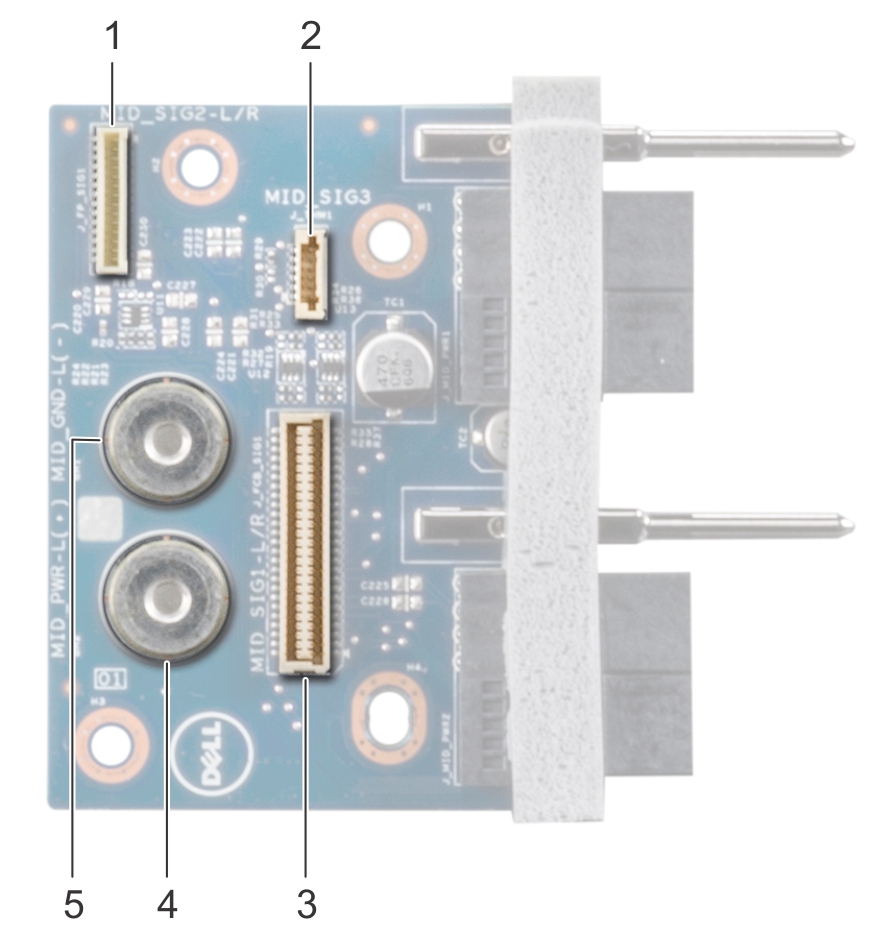
- Midplane signal connector 2
- Thermal sensor cable connector
- Chassis management board cable connector
- Midplane +12 V power cable connector
- Midplane power cable ground connector
Environmental specifications
The sections below contains information about the environmental specifications of the system.
Standard operating temperature specifications
- Not available: Indicates that the configuration is not offered by Dell EMC.
- Not supported: Indicates that the configuration is not thermally supported.
| Standard operating temperature | Specifications |
|---|---|
Temperature ranges (for altitude less than 950 m or 3117 ft) |
10°C–35°C (50°F–95°F) with no direct sunlight on the equipment. |
| TDP Watts | Processor model | Heat sink model | Max memory/processor | 3.5-inch chassis | 2.5-inch chassis | No-BP Chassis | |||||||
|---|---|---|---|---|---|---|---|---|---|---|---|---|---|
| 12x Drives | 8x Drives | 4x Drives | 24x Drives | 20x Drives | 16x Drives | 12x Drives | 8x Drives | 4x Drives | N/A | ||||
| 205 W | 8280 | CPU1: FMM2M | CPU2: V2DRD | CPU1: 6 | CPU2: 8 | Not Supported (2°C) | Not Supported (10°C) | Not Supported (11°C) | Not Supported(19°C) | 20 | 21 | 21 | 21 | 21 | 30 |
| 8280L | CPU1: FMM2M | CPU2: V2DRD | CPU1: 6 | CPU2: 8 | 20 | 21 | 21 | 21 | 21 | 30 | |||||
| 8280M | CPU1: FMM2M | CPU2: V2DRD | CPU1: 6 | CPU2: 8 | 20 | 21 | 21 | 21 | 21 | 30 | |||||
| 8270 | CPU1: FMM2M | CPU2: V2DRD | CPU1: 6 | CPU2: 8 | 20 | 21 | 21 | 21 | 21 | 30 | |||||
| 8268 | CPU1: FMM2M | CPU2: V2DRD | CPU1: 6 | CPU2: 8 | 20 | 21 | 21 | 21 | 21 | 30 | |||||
| 200 W | 6254 | CPU1: FMM2M | CPU2: V2DRD | CPU1: 6 | CPU2: 8 | Not Supported(6°C) | Not Supported(14°C) | Not Supported(15°C) | 20 | 21 | 22 | 22 | 22 | 22 | 30 |
| 165 W | 8276 | CPU1: JYKMM | CPU2: V2DRD | CPU1: 8 | CPU2: 8 | Not Supported(11°C) | Not Supported(18°C) | Not Supported(19°C) | 30 | 30 | 30 | 30 | 30 | 35 | 35 |
| 8276L | CPU1: JYKMM | CPU2: V2DRD | CPU1: 8 | CPU2: 8 | 30 | 30 | 30 | 30 | 30 | 35 | 35 | ||||
| 8276M | CPU1: JYKMM | CPU2: V2DRD | CPU1: 8 | CPU2: 8 | 30 | 30 | 30 | 30 | 30 | 35 | 35 | ||||
| 8260 | CPU1: JYKMM | CPU2: V2DRD | CPU1: 8 | CPU2: 8 | 30 | 30 | 30 | 30 | 30 | 35 | 35 | ||||
| 8260L | CPU1: JYKMM | CPU2: V2DRD | CPU1: 8 | CPU2: 8 | 30 | 30 | 30 | 30 | 30 | 35 | 35 | ||||
| 8260M | CPU1: JYKMM | CPU2: V2DRD | CPU1: 8 | CPU2: 8 | 30 | 30 | 30 | 30 | 30 | 35 | 35 | ||||
| 8260C | CPU1: JYKMM | CPU2: V2DRD | CPU1: 8 | CPU2: 8 | 30 | 30 | 30 | 30 | 30 | 35 | 35 | ||||
| 150 W | 6252 | CPU1: JYKMM | CPU2: V2DRD | CPU1: 8 | CPU2: 8 | Not Supported(14°C) | 21 | 23 | 30 | 30 | 30 | 30 | 30 | 35 | 35 |
| 6248 | CPU1: JYKMM | CPU2: V2DRD | CPU1: 8 | CPU2: 8 | 21 | 23 | 30 | 30 | 30 | 30 | 30 | 35 | 35 | ||
| 6240 | CPU1: JYKMM | CPU2: V2DRD | CPU1: 8 | CPU2: 8 | 21 | 23 | 30 | 30 | 30 | 30 | 30 | 35 | 35 | ||
| 6242 | CPU1: JYKMM | CPU2: V2DRD | CPU1: 8 | CPU2: 8 | 21 | 23 | 30 | 30 | 30 | 30 | 30 | 35 | 35 | ||
| 6244 | CPU1: FMM2M | CPU2: V2DRD | CPU1: 6 | CPU2: 8 | 21 | 23 | 30 | 30 | 30 | 30 | 30 | 35 | 35 | ||
| 6240C | CPU1: FMM2M | CPU2: V2DRD | CPU1: 6 | CPU2: 8 | 21 | 23 | 30 | 30 | 30 | 30 | 30 | 35 | 35 | ||
| 125 W | 6230 | CPU1: JYKMM | CPU2: V2DRD | CPU1: 8 | CPU2: 8 | 25 | 30 | 30 | 30 | 30 | 35 | 35 | 35 | 35 | 35 |
| 5220 | CPU1: JYKMM | CPU2: V2DRD | CPU1: 8 | CPU2: 8 | 25 | 30 | 30 | 30 | 30 | 35 | 35 | 35 | 35 | 35 | |
| 5218 | CPU1: JYKMM | CPU2: V2DRD | CPU1: 8 | CPU2: 8 | 25 | 30 | 30 | 30 | 30 | 35 | 35 | 35 | 35 | 35 | |
| 5218B | CPU1: JYKMM | CPU2: V2DRD | CPU1: 8 | CPU2: 8 | 25 | 30 | 30 | 30 | 30 | 35 | 35 | 35 | 35 | 35 | |
| 8253 | CPU1: JYKMM | CPU2: V2DRD | CPU1: 8 | CPU2: 8 | 25 | 30 | 30 | 30 | 30 | 35 | 35 | 35 | 35 | 35 | |
| 6238T | CPU1: JYKMM | CPU2: V2DRD | CPU1: 8 | CPU2: 8 | 25 | 30 | 30 | 30 | 30 | 35 | 35 | 35 | 35 | 35 | |
| 6230N | CPU1: JYKMM | CPU2: V2DRD | CPU1: 8 | CPU2: 8 | 25 | 30 | 30 | 30 | 30 | 35 | 35 | 35 | 35 | 35 | |
| 115 W | 5217 | CPU1: FMM2M | CPU2: V2DRD | CPU1: 6 | CPU2: 8 | 25 | 30 | 30 | 30 | 30 | 35 | 35 | 35 | 35 | 35 |
| 105 W | 5218T | CPU1: FMM2M | CPU2: V2DRD | CPU1: 6 | CPU2: 8 | 30 | 35 | 35 | 35 | 35 | 35 | 35 | 35 | 35 | 35 |
| 5218N | CPU1: FMM2M | CPU2: V2DRD | CPU1: 6 | CPU2: 8 | 30 | 35 | 35 | 35 | 35 | 35 | 35 | 35 | 35 | 35 | |
| 5222 | CPU1: FMM2M | CPU2: V2DRD | CPU1: 6 | CPU2: 8 | 30 | 35 | 35 | 35 | 35 | 35 | 35 | 35 | 35 | 35 | |
| 8256 | CPU1: FMM2M | CPU2: V2DRD | CPU1: 6 | CPU2: 8 | 30 | 35 | 35 | 35 | 35 | 35 | 35 | 35 | 35 | 35 | |
| 100 W | 4216 | CPU1: JYKMM | CPU2: V2DRD | CPU1: 8 | CPU2: 8 | 30 | 35 | 35 | 35 | 35 | 35 | 35 | 35 | 35 | 35 |
| 85 W | 5215 | CPU1: JYKMM | CPU2: V2DRD | CPU1: 8 | CPU2: 8 | 35 | 35 | 35 | 35 | 35 | 35 | 35 | 35 | 35 | 35 |
| 5215M | CPU1: JYKMM | CPU2: V2DRD | CPU1: 8 | CPU2: 8 | 35 | 35 | 35 | 35 | 35 | 35 | 35 | 35 | 35 | 35 | |
| 5215L | CPU1: JYKMM | CPU2: V2DRD | CPU1: 8 | CPU2: 8 | 35 | 35 | 35 | 35 | 35 | 35 | 35 | 35 | 35 | 35 | |
| 4215 | CPU1: JYKMM | CPU2: V2DRD | CPU1: 8 | CPU2: 8 | 35 | 35 | 35 | 35 | 35 | 35 | 35 | 35 | 35 | 35 | |
| 4214 | CPU1: JYKMM | CPU2: V2DRD | CPU1: 8 | CPU2: 8 | 35 | 35 | 35 | 35 | 35 | 35 | 35 | 35 | 35 | 35 | |
| 4214C | CPU1: JYKMM | CPU2: V2DRD | CPU1: 8 | CPU2: 8 | 35 | 35 | 35 | 35 | 35 | 35 | 35 | 35 | 35 | 35 | |
| 4210 | CPU1: JYKMM | CPU2: V2DRD | CPU1: 8 | CPU2: 8 | 35 | 35 | 35 | 35 | 35 | 35 | 35 | 35 | 35 | 35 | |
| 4208 | CPU1: JYKMM | CPU2: V2DRD | CPU1: 8 | CPU2: 8 | 35 | 35 | 35 | 35 | 35 | 35 | 35 | 35 | 35 | 35 | |
| 3204 | CPU1: JYKMM | CPU2: V2DRD | CPU1: 8 | CPU2: 8 | 35 | 35 | 35 | 35 | 35 | 35 | 35 | 35 | 35 | 35 | |
| 70 W | 4209T | CPU1: JYKMM | CPU2: V2DRD | CPU1: 8 | CPU2: 8 | 35 | 35 | 35 | 35 | 35 | 35 | 35 | 35 | 35 | 35 |
| TDP Watts | Processor model | Heat sink model | Max memory/processor | 3.5-inch chassis | 2.5-inch chassis | No-BP Chassis | |||||||
|---|---|---|---|---|---|---|---|---|---|---|---|---|---|
| 12x Drives | 8x Drives | 4x Drives | 24x Drives | 20x Drives | 16x Drives | 12x Drives | 8x Drives | 4x Drives | N/A | ||||
| 205W | 8280 | CPU1: FMM2M | CPU1: 6 | 30 | 30 | 30 | 35 | 35 | 35 | 35 | 35 | 35 | 35 |
| 8280L | CPU1: FMM2M | CPU1: 6 | 30 | 30 | 30 | 35 | 35 | 35 | 35 | 35 | 35 | 35 | |
| 8280M | CPU1: FMM2M | CPU1: 6 | 30 | 30 | 30 | 35 | 35 | 35 | 35 | 35 | 35 | 35 | |
| 8270 | CPU1: FMM2M | CPU1: 6 | 30 | 30 | 30 | 35 | 35 | 35 | 35 | 35 | 35 | 35 | |
| 8268 | CPU1: FMM2M | CPU1: 6 | 30 | 30 | 30 | 35 | 35 | 35 | 35 | 35 | 35 | 35 | |
| 200 W | 6254 | CPU1: FMM2M | CPU1: 6 | 30 | 30 | 30 | 35 | 35 | 35 | 35 | 35 | 35 | 35 |
| 165 W | 6212U | CPU1: JYKMM | CPU1: 8 | 30 | 35 | 35 | 35 | 35 | 35 | 35 | 35 | 35 | 35 |
| 8276 | CPU1: JYKMM | CPU1: 8 | 30 | 35 | 35 | 35 | 35 | 35 | 35 | 35 | 35 | 35 | |
| 8276L | CPU1: JYKMM | CPU1: 8 | 30 | 35 | 35 | 35 | 35 | 35 | 35 | 35 | 35 | 35 | |
| 8276M | CPU1: JYKMM | CPU1: 8 | 30 | 35 | 35 | 35 | 35 | 35 | 35 | 35 | 35 | 35 | |
| 8260 | CPU1: JYKMM | CPU1: 8 | 30 | 35 | 35 | 35 | 35 | 35 | 35 | 35 | 35 | 35 | |
| 8260L | CPU1: JYKMM | CPU1: 8 | 30 | 35 | 35 | 35 | 35 | 35 | 35 | 35 | 35 | 35 | |
| 8260M | CPU1: JYKMM | CPU1: 8 | 30 | 35 | 35 | 35 | 35 | 35 | 35 | 35 | 35 | 35 | |
| 8260C | CPU1: JYKMM | CPU1: 8 | 30 | 35 | 35 | 35 | 35 | 35 | 35 | 35 | 35 | 35 | |
| 150 W | 6210U | CPU1: JYKMM | CPU1: 8 | 30 | 35 | 35 | 35 | 35 | 35 | 35 | 35 | 35 | 35 |
| 6252 | CPU1: JYKMM | CPU1: 8 | 30 | 35 | 35 | 35 | 35 | 35 | 35 | 35 | 35 | 35 | |
| 6248 | CPU1: JYKMM | CPU1: 8 | 30 | 35 | 35 | 35 | 35 | 35 | 35 | 35 | 35 | 35 | |
| 6240 | CPU1: JYKMM | CPU1: 8 | 30 | 35 | 35 | 35 | 35 | 35 | 35 | 35 | 35 | 35 | |
| 6242 | CPU1: JYKMM | CPU1: 8 | 30 | 35 | 35 | 35 | 35 | 35 | 35 | 35 | 35 | 35 | |
| 6244 | CPU1: FMM2M | CPU1: 6 | 30 | 35 | 35 | 35 | 35 | 35 | 35 | 35 | 35 | 35 | |
| 6240C | CPU1: FMM2M | CPU1: 6 | 30 | 35 | 35 | 35 | 35 | 35 | 35 | 35 | 35 | 35 | |
| 125W | 6230 | CPU1: JYKMM | CPU1: 8 | 35 | 35 | 35 | 35 | 35 | 35 | 35 | 35 | 35 | 35 |
| 5220 | CPU1: JYKMM | CPU1: 8 | 35 | 35 | 35 | 35 | 35 | 35 | 35 | 35 | 35 | 35 | |
| 5218 | CPU1: JYKMM | CPU1: 8 | 35 | 35 | 35 | 35 | 35 | 35 | 35 | 35 | 35 | 35 | |
| 5218B | CPU1: JYKMM | CPU1: 8 | 35 | 35 | 35 | 35 | 35 | 35 | 35 | 35 | 35 | 35 | |
| 8253 | CPU1: JYKMM | CPU1: 8 | 35 | 35 | 35 | 35 | 35 | 35 | 35 | 35 | 35 | 35 | |
| 6238T | CPU1: JYKMM | CPU1: 8 | 35 | 35 | 35 | 35 | 35 | 35 | 35 | 35 | 35 | 35 | |
| 6230N | CPU1: JYKMM | CPU1: 8 | 35 | 35 | 35 | 35 | 35 | 35 | 35 | 35 | 35 | 35 | |
| 115 W | 5217 | CPU1: FMM2M | CPU1: 6 | 30 | 35 | 35 | 35 | 35 | 35 | 35 | 35 | 35 | 35 |
| 105 W | 5218T | CPU1: FMM2M | CPU1: 6 | 30 | 35 | 35 | 35 | 35 | 35 | 35 | 35 | 35 | 35 |
| 5218N | CPU1: FMM2M | CPU1: 6 | 30 | 35 | 35 | 35 | 35 | 35 | 35 | 35 | 35 | 35 | |
| 5222 | CPU1: FMM2M | CPU1: 6 | 30 | 35 | 35 | 35 | 35 | 35 | 35 | 35 | 35 | 35 | |
| 8256 | CPU1: FMM2M | CPU1: 6 | 30 | 35 | 35 | 35 | 35 | 35 | 35 | 35 | 35 | 35 | |
| 100 W | 4216 | CPU1: JYKMM | CPU1: 8 | 30 | 35 | 35 | 35 | 35 | 35 | 35 | 35 | 35 | 35 |
| 85 W | 5215 | CPU1: JYKMM | CPU1: 8 | 35 | 35 | 35 | 35 | 35 | 35 | 35 | 35 | 35 | 35 |
| 5215M | CPU1: JYKMM | CPU1: 8 | 35 | 35 | 35 | 35 | 35 | 35 | 35 | 35 | 35 | 35 | |
| 5215L | CPU1: JYKMM | CPU1: 8 | 35 | 35 | 35 | 35 | 35 | 35 | 35 | 35 | 35 | 35 | |
| 4215 | CPU1: JYKMM | CPU1: 8 | 35 | 35 | 35 | 35 | 35 | 35 | 35 | 35 | 35 | 35 | |
| 4214 | CPU1: JYKMM | CPU1: 8 | 35 | 35 | 35 | 35 | 35 | 35 | 35 | 35 | 35 | 35 | |
| 4214C | CPU1: JYKMM | CPU1: 8 | 35 | 35 | 35 | 35 | 35 | 35 | 35 | 35 | 35 | 35 | |
| 4210 | CPU1: JYKMM | CPU1: 8 | 35 | 35 | 35 | 35 | 35 | 35 | 35 | 35 | 35 | 35 | |
| 4208 | CPU1: JYKMM | CPU1: 8 | 35 | 35 | 35 | 35 | 35 | 35 | 35 | 35 | 35 | 35 | |
| 3204 | CPU1: JYKMM | CPU1: 8 | 35 | 35 | 35 | 35 | 35 | 35 | 35 | 35 | 35 | 35 | |
| 70 W | 4209T | CPU1: JYKMM | CPU1: 8 | 35 | 35 | 35 | 35 | 35 | 35 | 35 | 35 | 35 | 35 |
| TDP Watts | 3.5-inch chassis | 2.5-inch chassis | No-BP Chassis | |||||
|---|---|---|---|---|---|---|---|---|
| 12x HDDs | 8x HDDs | 4x HDDs | 24x HDDs | 16x HDDs | 8x HDDs | 4x HDDs | N/A | |
| 205 W | Not supported | Not supported | Not supported | Not supported | Not supported | Not supported | Not supported | 23 |
| 200 W | Not supported | Not supported | Not supported | Not supported | Not supported | Not supported | Not supported | 23 |
| 173 W | Not supported | Not supported | Not supported | Not supported | Not supported | 24 | 24 | 28 |
| 165 W | Not supported | Not supported | Not supported | 24 | 25 | 25 | 26 | 29 |
| 160 W | Not supported | Not supported | Not supported | 24 | 25 | 26 | 26 | 30 |
| 150 W | Not supported | Not supported | Not supported | 26 | 27 | 28 | 28 | 31 |
| 140 W | Not supported | 23 | 25 | 28 | 29 | 29 | 30 | 33 |
| 135 W | Not supported | 24 | 25 | 29 | 30 | 30 | 31 | 33 |
| 130 W | Not supported | 24 | 26 | 30 | 31 | 31 | 31 | 34 |
| 125 W | 20 | 25 | 27 | 30 | 31 | 32 | 32 | 35 |
| 115 W | 21 | 27 | 28 | 32 | 33 | 34 | 34 | >35 |
| 113 W | 21 | 27 | 28 | 32 | 33 | 34 | 34 | >35 |
| 105 W | 22 | 28 | 30 | 34 | 35 | >35 | >35 | >35 |
| 85 W | 23 | 32 | 33 | >35 | >35 | >35 | >35 | >35 |
| 70 W | 25 | 34 | >35 | >35 | >35 | >35 | >35 | >35 |
| TDP Watts | 3.5-inch chassis | 2.5-inch chassis | No-BP Chassis | |||||
|---|---|---|---|---|---|---|---|---|
| 12x HDDs | 8x HDDs | 4x HDDs | 24x HDDs | 16x HDDs | 8x HDDs | 4x HDDs | N/A | |
| 205 W | Not supported | Not supported | Not supported | Not supported | Not supported | 20 | 20 | 23 |
| 200 W | Not supported | Not supported | Not supported | Not supported | Not supported | 21 | 21 | 24 |
| 173 W | Not supported | Not supported | Not supported | 20 | 20 | 23 | 24 | 28 |
| 165 W | Not supported | Not supported | Not supported | 22 | 22 | 24 | 25 | 29 |
| 160 W | Not supported | Not supported | Not supported | 22 | 22 | 24 | 26 | 29 |
| 150 W | Not supported | Not supported | Not supported | 24 | 24 | 26 | 27 | 30 |
| 140 W | Not supported | Not supported | Not supported | 26 | 26 | 27 | 28 | 31 |
| 135 W | Not supported | Not supported | 20 | 26 | 26 | 28 | 29 | 32 |
| 130 W | Not supported | Not supported | 20 | 27 | 27 | 29 | 29 | 33 |
| 125 W | Not supported | Not supported | 21 | 28 | 28 | 30 | 30 | 33 |
| 115W | Not supported | 21 | 23 | 29 | 31 | 31 | 32 | 34 |
| 105 W | 20 | 23 | 24 | 30 | 33 | 33 | 34 | >35 |
| 85 W | 24 | 26 | 27 | 34 | >35 | >35 | >35 | >35 |
| 70 W | 25 | 28 | 29 | >35 | >35 | >35 | >35 | >35 |
| TDP Watts | 3.5-inch chassis | 2.5-inch chassis | No-BP Chassis | |||||
|---|---|---|---|---|---|---|---|---|
| 12x HDDs | 8x HDDs | 4x HDDs | 24x HDDs | 16x HDDs | 8x HDDs | 4x HDDs | N/A | |
| 205 W | Not supported | Not supported | Not supported | Not supported | Not supported | Not supported | Not supported | Not supported |
| 200 W | Not supported | Not supported | Not supported | Not supported | Not supported | Not supported | Not supported | Not supported |
| 173 W | Not supported | Not supported | Not supported | Not supported | Not supported | Not supported | Not supported | 20 |
| 165 W | Not supported | Not supported | Not supported | Not supported | Not supported | Not supported | Not supported | 20 |
| 160 W | Not supported | Not supported | Not supported | Not supported | Not supported | Not supported | Not supported | 25 |
| 150 W | Not supported | Not supported | Not supported | Not supported | 20 | 20 | 20 | 25 |
| 140 W | Not supported | Not supported | Not supported | 20 | 20 | 20 | 20 | 25 |
| 135 W | Not supported | Not supported | Not supported | 20 | 20 | 20 | 20 | 25 |
| 130 W | Not supported | Not supported | Not supported | 20 | 20 | 20 | 20 | 25 |
| 125 W | Not supported | Not supported | Not supported | 20 | 25 | 25 | 25 | 30 |
| 115 W | Not supported | Not supported | Not supported | 25 | 25 | 25 | 25 | 30 |
| 105 W | Not supported | Not supported | Not supported | 25 | 25 | 25 | 25 | 30 |
| 85 W | Not supported | Not supported | Not supported | 30 | 30 | 30 | 30 | >35 |
| 70 W | Not supported | Not supported | Not supported | >35 | >35 | >35 | >35 | >35 |
Expanded operating temperature specifications
| Expanded operating temperature | Specifications |
|---|---|
| Continuous operation | 5°C–40°C at 5% to 85% RH with maximum 29°C dew point. NOTE: Outside the standard
operating temperature (10°C–35°C), the system can operate continuously
in temperatures as low as 5°C and as high as 40°C. |
| For temperatures between 35°C and 40°C, derate maximum allowable temperature by 1°C per 175 m above 950 m (1°F per 319 ft). | |
| ≤ 1% of annual operating hours | –5°C–45°C at 5% to 90% RH with maximum 29°C dew point. NOTE: Outside the standard
operating temperature (10°C–35°C), the system can operate down
to –5°C or up to 45°C for a maximum of 1% of its annual operating
hours. |
| For temperatures between 40°C-45°C, derate maximum allowable temperature by 1°C per 125 m above 950 m (1°F per 228 ft). |
Operating temperature derating specifications
| Operating temperature derating | Specifications |
|---|---|
< 35°C (95°F) |
Maximum temperature is reduced by 1°C/300 m (1°F/547 ft) above 950 meters (3,117 ft). |
35°C–40°C (95°F–104°F) |
Maximum temperature is reduced by 1°C/175 m (1°F/319 ft) above 950 meters (3,117 ft). |
> 45°C (113°F) |
Maximum temperature is reduced by 1°C/125 m (1°F/228 ft) above 950 meters (3,117 ft). |
Relative humidity specifications
| Relative humidity | Specifications |
|---|---|
Storage |
5% to 95% RH with 33°C (91°F) maximum dew point. Atmosphere must be noncondensing always. |
Operating |
10% to 80% relative humidity with 29°C (84.2°F) maximum dew point. |
Temperature specifications
Temperature |
Specifications |
|---|---|
Storage |
–40°C–65°C (–40°F to 149°F) |
Continuous operation (for altitude less than 950 m or 3117 ft) |
10°C–35°C (50°F to 95°F) with no direct sunlight on the equipment. |
Fresh air |
For information about fresh air, see Expanded Operating Temperature section. |
Maximum temperature gradient (operating and storage) |
20°C/h (68°F/h) |
Particulate and gaseous contamination specifications
| Particulate contamination | Specifications |
|---|---|
| Air filtration | Data center air filtration as defined by ISO Class 8 per ISO 14644-1 with a 95% upper confidence limit. |
|
NOTE: This condition applies only to data center environments. Air filtration requirements do not apply to IT equipment designed to be used outside a data center, in environments such as an office or factory floor.
|
|
|
NOTE: Air entering the data center must have MERV11 or MERV13 filtration.
|
|
| Conductive dust | Air must be free of conductive dust, zinc whiskers, or other conductive particles. |
|
NOTE: This condition applies to data center and non-data center environments.
|
|
| Corrosive dust | Air must be free of corrosive dust. |
| Residual dust present in the air must have a deliquescent point less than 60% relative humidity. | |
|
NOTE: This condition applies to data center and non-data center environments.
|
|
| Gaseous contamination | Specifications |
|---|---|
| Copper coupon corrosion rate | <300 Å/month per Class G1 as defined by ANSI/ISA71.04-2013 |
| Silver coupon corrosion rate | <200 Å/month per Class G1 as defined by ANSI/ISA71.04-2013 |
|
NOTE: Maximum corrosive contaminant levels measured at ≤50% relative humidity.
|
|
Maximum vibration specifications
| Maximum vibration | Specifications |
|---|---|
| Operating | 0.26 Grms at 5 Hz to 350 Hz (all operation orientations). |
| Storage | 1.88 Grms at 10 Hz to 500 Hz for 15 min (all six sides tested). |
Maximum shock specifications
| Maximum shock | Specifications |
|---|---|
| Operating | 24 executed shock pulses 6 G in the positive and negative x, y, z axis for up to 11 ms (four pulses on each side of the system). |
| Storage | 6 consecutively executed shock pulses of 71 G in the positive and negative x, y, z axes for up to 2 ms (one pulse on each side of the system). |
Maximum altitude specifications
| Maximum altitude | Specifications |
|---|---|
| Operating | 3048 m (10,000 ft) |
| Storage | 12,000 m (39,370 ft) |
Fresh Air Operation
Fresh Air operation restrictions
- Processors with a TDP greater than 105 W are not supported
- Support for processors of 85 W and below without PERC restrictions
- 3.5-inch drive configuration is not supported
- 114-mm heat sink is required for the processor in CPU1 socket
- Kerby-flat OCP is not supported
- M.2 card on DCS Mezzanine slot is not supported.
- NVMe SSD is not supported
- AEP DIMM and LRDIMM are not supported
- PCIe cards greater than 25 W are not supported
- H730 PERC and H330 support for 105-W processors
- No PERC restrictions for 85 W and lesser TDP processors