




























Chassis dimensions
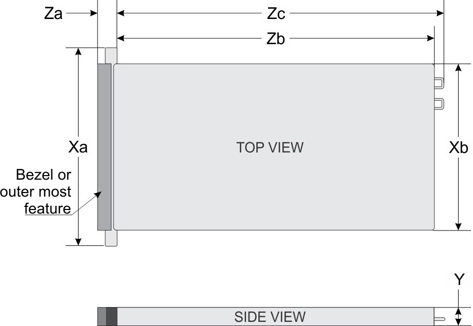
| Xa | Xb | Y | Za | Zb* | Zc |
|---|---|---|---|---|---|
| 482.4 mm (18.99 inches) | 434 mm (17.08 inches) | 43.1 mm (1.69 inches) | 18.0 mm (0.70 inches) | 886.4 mm (34.89 inches) | 923.8 mm (36.37 inches) |
* - Zb goes to the nominal rear wall external surface where the system board I/O connectors are located.
System weight
| System | Maximum weight |
|---|---|
| PowerEdge C4140 (Configuration C - with PCIe GPUs) | 22.1 kg (48.7 lb) |
| PowerEdge C4140 (Configuration K - with SXM2 GPUs) | 24 kg (52.91 lb) |
GPU specifications
- NVIDIA Tesla P40
- NVIDIA Tesla P100 12 GB PCIe
- NVIDIA Tesla P100 16 GB PCIe and NVLink
- NVIDIA Tesla V100 16 GB PCIe and NVLink
- NVIDIA Tesla V100 32GB PCIe and NVLINK
Processor specifications
Supported operating systems
- Canonical Ubuntu LTS
- Citrix XenServer
- Microsoft Windows Server
- Red Hat Enterprise Linux
- SUSE Linux Enterprise Server
- VMware ESXi
PSU specifications
The Dell EMC PowerEdge C4140 system supports the following AC power supply units (PSU):
| PSU | Class | Heat dissipation (maximum) | Frequency | Voltage | AC | Current | |
|---|---|---|---|---|---|---|---|
| High line 100–240 V | Low line 100–120 V | ||||||
| 2400 W AC | Titanium | 9000 BTU/hr | 50/60 Hz | 100–240 V AC, autoranging | 2400 W | NA | 16 A |
| 2000 W AC | Platinum | 7500 BTU/hr | 50/60 Hz | 100–240 V AC, autoranging | 2000 W | NA | 11.5 A |
- Heat dissipation is calculated using the PSU wattage rating.
- This system is also designed to connect to the IT power systems with a phase-to-phase voltage not exceeding 240 V.
Cooling fans specifications
| Processor count | Fan 1 | Fan 2 | Fan 3 | Fan 4 | Fan 5 | Fan 6 | Fan 7 | Fan 8 |
|---|---|---|---|---|---|---|---|---|
| 2 | Required | Required | Required | Required | Required | Required | Required | Required |
System battery specifications
The PowerEdge C4140 system supports CR 2032 lithium coin cell system battery.
Expansion bus specifications
The PowerEdge C4140 system supports PCI express (PCIe) generation 3 expansion cards, which are installed on the system, using expansion card risers. This system supports two risers, riser 1A and riser 2A.
Memory specifications
| DIMM type | DIMM rank | DIMM capacity | Dual processors | |
|---|---|---|---|---|
| Minimum RAM | Maximum RAM | |||
| LRDIMM | Quad rank | 64 GB | 128 GB | 1536 GB |
| RDIMM | Dual rank | 64 GB | 128 GB | 1536 GB |
| RDIMM | Dual rank | 32 GB | 64 GB | 768 GB |
| RDIMM | Dual rank | 16 GB | 32 GB | 384 GB |
| RDIMM | Single rank | 8 GB | 16 GB | 192 GB |
- Ensure that all the memory slots are populated either with DIMMs or DIMM blanks.
- It is recommended to have all DIMMs of same type.
Storage specifications
| Internal controllers | External controllers |
|---|---|
|
One BOSS PCIe card with M.2 SATA SSDs Up to two NVMe/PCIe SSDs as internal storage Up to 2 NVMe add-in cards in slots 1 and 3 |
12 Gbps SAS HBA H840 |
Drive specifications
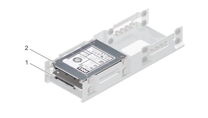
- HDD1
- HDD0
USB ports
The PowerEdge C4140 system supports:
- Two USB 3.0-compliant ports on the back panel
- One internal USB 3.0-compliant port
NIC ports
Serial port
The PowerEdge C4140 system supports one serial port on the rear view. This port is a 9-pin connector, Data Terminal Equipment (DTE), 16550-compliant.
VGA ports
The Video Graphic Array (VGA) port enables you to connect the system to a VGA display. The PowerEdge C4140 system supports one 15-pin VGA port on the back of system.
Video specifications
| Resolution | Refresh rate (Hz) | Color depth (bit) |
|---|---|---|
| 640 X 480 | 60, 70 | 8, 16, 32 |
| 800 X 600 | 60, 75, 85 | 8, 16, 32 |
| 1024 X 768 | 60, 75, 85 | 8, 16, 32 |
| 1152 X 864 | 60, 75, 85 | 8, 16, 32 |
| 1280 X 1024 | 60, 75 | 8, 16, 32 |
| 1440 X 900 | 60 | 8, 16, 32 |
| 1920 x 1200 | 60 | 8, 16, 32 |
Environmental specifications
| Temperature | Specifications |
|---|---|
| Storage | –40°C to 65°C (–40°F to 149°F) |
| Continuous operation (for altitude less than 950 m or 3117 ft) | 10°C to 30°C (50°F to 86°F) with no direct sunlight
on the equipment. NOTE Certain system hardware configurations may require operating temperatures
to be less than 25°C. For more information, see the Ambient temperature
limitations section. |
| Fresh air | For information about fresh air, see Expanded Operating Temperature section. |
| Maximum temperature gradient (operating and storage) | 20°C/h (68°F/h) |
| Relative humidity | Specifications |
|---|---|
| Storage | 5% to 95% RH with 33°C (91°F) maximum dew point. Atmosphere must be non-condensing at all times. |
| Operating | 10% to 80% relative humidity with 29°C (84.2°F) maximum dew point. |
| Maximum vibration | Specifications |
|---|---|
| Operating | 0.26 Grms at 5 Hz to 350 Hz (all operation orientations). |
| Storage | 1.88 Grms at 10 Hz to 500 Hz for 15 min (all six sides tested). |
| Maximum shock | Specifications |
|---|---|
| Operating | Six consecutively executed shock pulses in the positive and negative x, y, and z axes of 6 G for up to 11 ms. |
| Storage | Six consecutively executed shock pulses in the positive and negative x, y, and z axes (one pulse on each side of the system) of 71 G for up to 2 ms. |
| Maximum altitude | Specifications |
|---|---|
| Operating | 3048 m (10,000 ft) |
| Storage | 12,000 m (39,370 ft) |
| Operating temperature de-rating | Specifications |
|---|---|
| Up to 30°C (86°F) | Maximum temperature is reduced by 1°C/300 m (1°F/547 ft) above 950 m (3,117 ft). |
Standard operating temperature
| Standard operating temperature | Specifications |
|---|---|
| Continuous operation (for altitude less than 950 m or 3117 ft) | 10°C to 30°C (50°F to 86°F) with no direct sunlight on the equipment. |
Maximum recommended ambient operating temperature
| CPU Power Dissipation / GPU Power (4x) | 2x 70 W | 2x 85 W | 2x 10⁵ W | 2x 125 W | 2x 130 W | 2x 140 W | 2x 150 W | 2x 165 W |
|---|---|---|---|---|---|---|---|---|
| 325 W | 21 | 21 | 20 | 19 | 19 | 18 | 17 | 15 |
| 300 W | 23 | 23 | 22 | 21 | 21 | 20 | 19 | 17 |
| 275 W | 25 | 25 | 24 | 23 | 23 | 22 | 21 | 19 |
| 250 W | 27 | 26 | 26 | 25 | 25 | 24 | 23 | 22 |
| 225 W | 29 | 28 | 28 | 27 | 27 | 26 | 25 | 24 |
| 200 W | 30 | 30 | 30 | 30 | 29 | 28 | 27 | 26 |
| CPU Power Dissipation / GPU Power (4x) | 2x 70 W | 2x 85 W | 2x 10⁵ W | 2x 125 W | 2x 130 W | 2x 140 W | 2x 150 W | 2x 165 W |
|---|---|---|---|---|---|---|---|---|
| 325 W | 24 | 23 | 22 | 21 | 20 | 20 | 19 | 17 |
| 300 W | 28 | 26 | 24 | 23 | 23 | 23 | 22 | 20 |
| 275 W | 28 | 27 | 26 | 25 | 25 | 24 | 23 | 21 |
| 250 W | 30 | 29 | 28 | 27 | 26 | 26 | 25 | 23 |
| 225 W | 30 | 30 | 30 | 29 | 28 | 28 | 28 | 26 |
| 200 W | 30 | 30 | 30 | 30 | 30 | 30 | 30 | 28 |
| CPU Power Dissipation / GPU Power (4x) | 2x 70 W | 2x 85 W | 2x 10⁵ W | 2x 125 W | 2x 130 W | 2x 140 W | 2x 150 W | 2x 165 W |
|---|---|---|---|---|---|---|---|---|
| 325 W | 23 | 22 | 20 | 19 | 18 | 18 | 18 | 17 |
| 300 W | 25 | 24 | 22 | 21 | 21 | 20 | 19 | 18 |
| 275 W | 27 | 26 | 23 | 23 | 23 | 22 | 21 | 20 |
| 250 W | 28 | 27 | 25 | 25 | 25 | 24 | 23 | 22 |
| 225 W | 30 | 29 | 27 | 27 | 27 | 26 | 25 | 24 |
| 200 W | 30 | 30 | 29 | 29 | 29 | 28 | 27 | 26 |
| CPU Power Dissipation / NVLink SXM2 | 2x 70 W | 2x 85 W | 2x 10⁵ W | 2x 125 W | 2x 130 W | 2x 140 W | 2x 150 W | 2x 165 W |
|---|---|---|---|---|---|---|---|---|
| 300W | 25 | 24 | 22 | 21 | 20 | 19 | 18 | 18 |
| CPU Power Dissipation / NVLink SXM2 | 2x 70 W | 2x 85 W | 2x 10⁵ W | 2x 125 W | 2x 130 W | 2x 140 W | 2x 150 W | 2x 165 W |
|---|---|---|---|---|---|---|---|---|
| 300W | 24 | 24 | 23 | 23 | 22 | 22 | 20 | 20 |
Particulate and gaseous contamination specifications
| Particulate contamination | Specifications |
|---|---|
| Air filtration | Data center air filtration as defined by ISO Class
8 per ISO 14644-1 with a 95% upper confidence limit. NOTE This condition applies
to data center environments only. Air filtration requirements do not
apply to IT equipment designed to be used outside a data center, in
environments such as an office or factory floor. NOTE Air entering the data
center must have the MERV11 or MERV13 filtration. |
| Conductive dust | Air must be free of conductive dust, zinc whiskers,
or other conductive particles. NOTE This condition applies
to data center and non-data center environments. |
| Corrosive dust |
NOTE This condition
applies to data center and non-data center environments. |
| Gaseous contamination | Specifications |
|---|---|
| Copper coupon corrosion rate | <300 Å/month per Class G1 as defined byANSI/ISA71.04-2013. |
| Silver coupon corrosion rate | <200 Å/month as defined by ANSI/ISA71.04-2013. |