




























Product specifications
| Feature | Overview |
|---|---|
| Processor | Intel Denverton-L (C3000 family) 10.75 W 1.3 GHz |
| Intel CPU SKU | C3436L (4-core) |
| Chipset | North and south bridge that is built into the CPU/SOC |
| Memory | 8 GB DDR4 |
| Out of band management | Micro-USB console |
| Mounting options | Desktop, wall mount, or rack mount (1.5 RU, dual unit tray) |
| Dimension | 208 mm x 52 mm x 200 mm (W x H x D) |
| Weight | 1.3 kg to 1.4 kg |
| Power consumption | VEP1420N:
VEP1420:
VEP1420-LTE:
|
| Airflow | The VEP1420 and VEP1420-LTE models have one fan inlet at the bottom, with the exhaust ports on the sides and on the back. The VEP1420N is fan-less. |
| Power supply | External AC/DC power adapter, 110-240 VAC, 50 Hz–60 Hz, 12 V DC |
| TPM | Chips onboard support TPM 2.0, Infineon P/N SLB9665VQ2.0 (firmware version 5.63). |
| Serviceability | No field upgradable components |
| USB | 2x SuperSpeed USB 3.0 ports on both sides of the enclosure |
| BIOS | AMI BIOS |
| BMC | No BMC |
Wireless specifications
The following table provides the wireless technologies that each model supports:
| Wireless technology | ||||
|---|---|---|---|---|
| Dell model number | WiFi | WWAN: LTE | GNSS | Notes |
| VEP1420N | No | No | No |
NOTE:The VEP1420N does not support any wireless functionality.
|
| VEP1420 | Yes | No | No |
NOTE:The VEP1420 provides two internal WiFi antennas for dual-band WiFi.
|
| VEP1420-LTE | Yes | Yes | Yes |
NOTE:The VEP1420-LTE provides two internal WiFi antennas for dual-band WiFi.
NOTE:The VEP1420-LTE provides two external antennas for 3G or 4G.
For more information, see GNSS specifications. |
| Dell model number | WiFi | WWAN and GNSS |
|---|---|---|
| VEP1420N | N/A | N/A |
| VEP1420 | Compex WLE3002HX | N/A |
| VEP1420-LTE | Compex WLE3002HX | Sierra Wireless EM7565 |
| Feature | Overview |
|---|---|
| 4G LTE (Long-Term Evolution) |
|
| 3G WCDMA (Wideband Code Division Multiple Access) |
|
| SIM Card Support |
|
| GNSS (Global Navigation Satellite System) |
|
| WiFi Dual Band |
|
| Antennas |
|
WWAN 4G LTE specifications
This section provides information on the WWAN 4G LTE specifications. These specifications are applicable only to the VEP1420-LTE.
LTE bands and frequencies
The embedded device in the VEP1420-LTE supports the following LTE bands:
| Band | Frequency (Tx) | Frequency (Rx) |
|---|---|---|
| B1 | 1920 MHz–1980 MHz | 2110 MHz–2170 MHz |
| B2 | 1850 MHz–1910 MHz | 1930 MHz–1990 MHz |
| B3 | 1710 MHz–1785 MHz | 1805 MHz–1880 MHz |
| B4 | 1710 MHz–1755 MHz | 2110 MHz–2155 MHz |
| B5 | 824 MHz–849 MHz | 869 MHz–894 MHz |
| B7 | 2500 -2570 MHz | 2620 MHz–2690 MHz |
| B8 | 880 MHz–915 MHz | 925 MHz–960 MHz |
| B9 | 1749.9 - 1784.9 MHz | 1844.9 - 1879.9 MHz |
| B12 | 699 MHz–716 MHz | 729 MHz–746 MHz |
| B13 | 777 MHz–787 MHz | 746 MHz–756 MHz |
| B18 | 815 MHz–830 MHz | 860 MHz–875 MHz |
| B19 | 830 MHz–845 MHz | 875 MHz–890 MHz |
| B20 | 832 MHz–862 MHz | 791 MHz–821 MHz |
| B26 | 814 MHz–849 MHz | 859 MHz–894 MHz |
| B28 | 703 MHz–748 MHz | 758 MHz–803 MHz |
| B29 | N/A | 717 MHz–728 MHz |
| B30 | 2305 MHz–2315 MHz (Download only) | 2350 MHz–2360 MHz |
| B32 | N/A | 1452 MHz–1496 MHz |
| B41 | 2496 MHz–2690 MHz (TDD) | |
| B42a | 3400 MHz–3600 MHz (TDD) | |
| B43a ** | 3600 MHz–3800 MHz (TDD) | |
| B46 | N/A | 5150 MHz–5925 MHz (TDD) |
| B48a ** | 3550 MHz–3700 MHz (TDD) | |
| B66 | 1710 MHz–1780 MHz | 2110 MHz–2200 MHz |
** When operating in the US, you must disable Band 43 and Band 48(CBRS) to meet FCC regulatory requirements.
LTE transmit power
The following table provides the LTE conducted power out of the embedded module for all the bands that the VEP1420-LTE supports. The total radiated power depends on the antenna efficiency.
| LTE Bands | Conducted Tx power | Notes |
|---|---|---|
| 1,2,3,4,5,8,9,12,13,18,19,20,26,28,66 | +23 dBm +/- 1 dB |
NOTE: Conducted transmitted power out of an internal module. Does not include antenna gain or internal cable losses.
|
| 7, 41 |
Single cell: +22 dBm +/- 1 dB UL CA: +22.8 dBm +/- 1 dB |
|
| 42, 43,48 ** | +22 dBm +/- 1 dB |
NOTE: **When operating in the US, you must disable Band 43 and Band 48(CBRS) to meet FCC regulatory requirements.
|
LTE receiver sensitivity
The following LTE receiver sensitivity levels are the conducted sensitivity values that are provided by the internal embedded module. Sensitivity of the device depends upon the antenna efficiency in the band of interest and the environment in which the device is used.
| LTE bands | Conducted Rx sensitivity (dBm) | ||||
|---|---|---|---|---|---|
| Primary (Type) | Secondary (Type) | SIMO (Type) | SIMOa (Worst case) | ||
| B1 | Full RB on downlink; BW: 20 MHz | -97.5 | -97.5 | -100.0 | -96.3 |
| B2 | -98.0 | -97.5 | -100.5 | -94.3 | |
| B3 | -97.0 | -98.0 | -100.5 | -93.3 | |
| B4 | -97.0 | -98.0 | -100.0 | -96.3 | |
| B5 | -99.0 | -100.5 | -102.5 | -94.3 | |
| B7 | -97.0 | -99.0 | -101.0 | -94.3 | |
| B8 | -98.5 | -100.5 | -102.5 | -94.3 | |
| B9 | -97.0 | -98.5 | -100.5 | -95.3 | |
| B12 | -98.0 | -101.0 | -102.5 | -93.3 | |
| B13 | -98.0 | -101.0 | -103.0 | -93.3 | |
| B18 | -99.0 | -101.0 | -103.0 | -96.3 | |
| B19 | -98.5 | -100.5 | -102.5 | -96.3 | |
| B20 | -98.5 | -101.0 | -103.5 | -93.3 | |
| B26 | -99.0 | -100.5 | -102.5 | -93.8 | |
| B28 | -98.5 | -100.5 | -102.5 | -94.8 | |
| B29 | -97.0 | -101.0 | -102.5 | -93.3 | |
| B30 | -97.0 | -99.0 | -101.0 | -95.3 | |
| B32 | -99.5 | -98.0 | -101.5 | -96.3 | |
| B41 | -96.5 | -98.0 | -100.5 | -94.3 | |
| B42 | -97.0 | -98.5 | -101.0 | -95.0 | |
| B43 | -97.0 | -97.5 | -101.0 | -95.0 | |
| B48 | -97.0 | -98.0 | -101.0 | -95.3 | |
| B66 | -97.0 | -98.0 | -100.0 | -95.8 | |
| B46 | Full RB on downlink; BW: 20 MHz | -96.5 | -97.0 | -99.0 | -88.5 |
WWAN 3G WCDMA specifications
This section provides information about the WWAN 3G WCDMA specifications. The WWAN 3G WCDMA specifications are applicable only to the VEP1420-LTE.
Bands and frequencies
The embedded device in the VEP1420-LTE supports the following 3G bands:
| Band | Frequency (Tx) | Frequency (Rx) |
|---|---|---|
| B1 | 1920 MHz–1980 MHz | 2110 MHz–2170 MHz |
| B2 | 1850 MHz–1910 MHz | 1930 MHz–1990 MHz |
| B4 | 1710 MHz–1755 MHz | 2110 MHz–2155 MHz |
| B5 | 824 MHz–849 MHz | 869 MHz–894 MHz |
| B6 | 830 MHz-840 MHz | 875 MHz–885 MHz |
| B8 | 880 MHz–915 MHz | 925 MHz–960 MHz |
| B9 | 1749.9 MHz-1784.9 MHz | 1844.9 MHz-1879.9 MHz |
| B19 | 830 MHz–845 MHz | 875 MHz–890 MHz |
3G WCDMA transmit power
The following table provides the 3G WCDMA conducted power out of the embedded module for all the bands that the VEP1420-LTE supports. The total radiated power depends on the antenna efficiency.
| 3G WCDMA Bands | Transmit power | Notes |
|---|---|---|
| All supported UMTS bands1,2,4,5,6,8,9,19 | +23 dBm +/- 1 dBm |
NOTE: Conducted transmitted power out of an internal module. These values does not include antenna gain or internal cable losses.
|
3G WCDMA receiver sensitivity
The following 3G WCDMA receiver sensitivity levels are the conducted sensitivity values that are provided by the internal embedded module. Sensitivity of the device depends upon the antenna efficiency in the band of interest and the environment in which the device is used.
| WCDMA bands | Conducted sensitivity (dBm) | |||
|---|---|---|---|---|
| Band | Sensitivity criteria | Main port | AUX port | Main/AUX Worst case |
| B1 | 0.1% BER 12.2 Kb/s | -110.6 | -110.5 | -106.7 |
| B2 | -111.2 | -110.4 | -104.7 | |
| B4 | -110.1 | -110.6 | -106.7 | |
| B5 | -111.4 | -113.5 | -100.0 | |
| B6 | -111.2 | -113.4 | -103.7 | |
| B8 | -111.4 | -113.4 | -103.7 | |
| B9 | -110.1 | -111.3 | -105.7 | |
| B19 | -111.1 | -113.4 | -106.7 | |
WWAN antennas
Two WWAN antennas are provided with the VEP1420-LTE switch. These antennas are installed on the following two RF ports that are labeled MAIN and AUX:
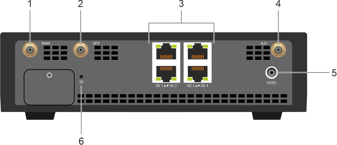
| Figure legend | Description |
|---|---|
| 1 | SMA jack mount corresponding to the Main RF port on the VEP1420-LTE. |
| 2 | SMA jack mount for the GPS antenna |
| 4 | SMA jack mount corresponding to the AUX RF port on the VEP1420-LTE. |
The MAIN port of the VEP1420-LTE is both a transmit and receive port for the modem. This port is required by the modem to connect to a network. The AUX port is a receiver port only and does not transmit. The AUX port provides additional receiver sensitivity for the LTE or WCDMA. The AUX port also provides GNSS receiver capability using the WWAN antenna.
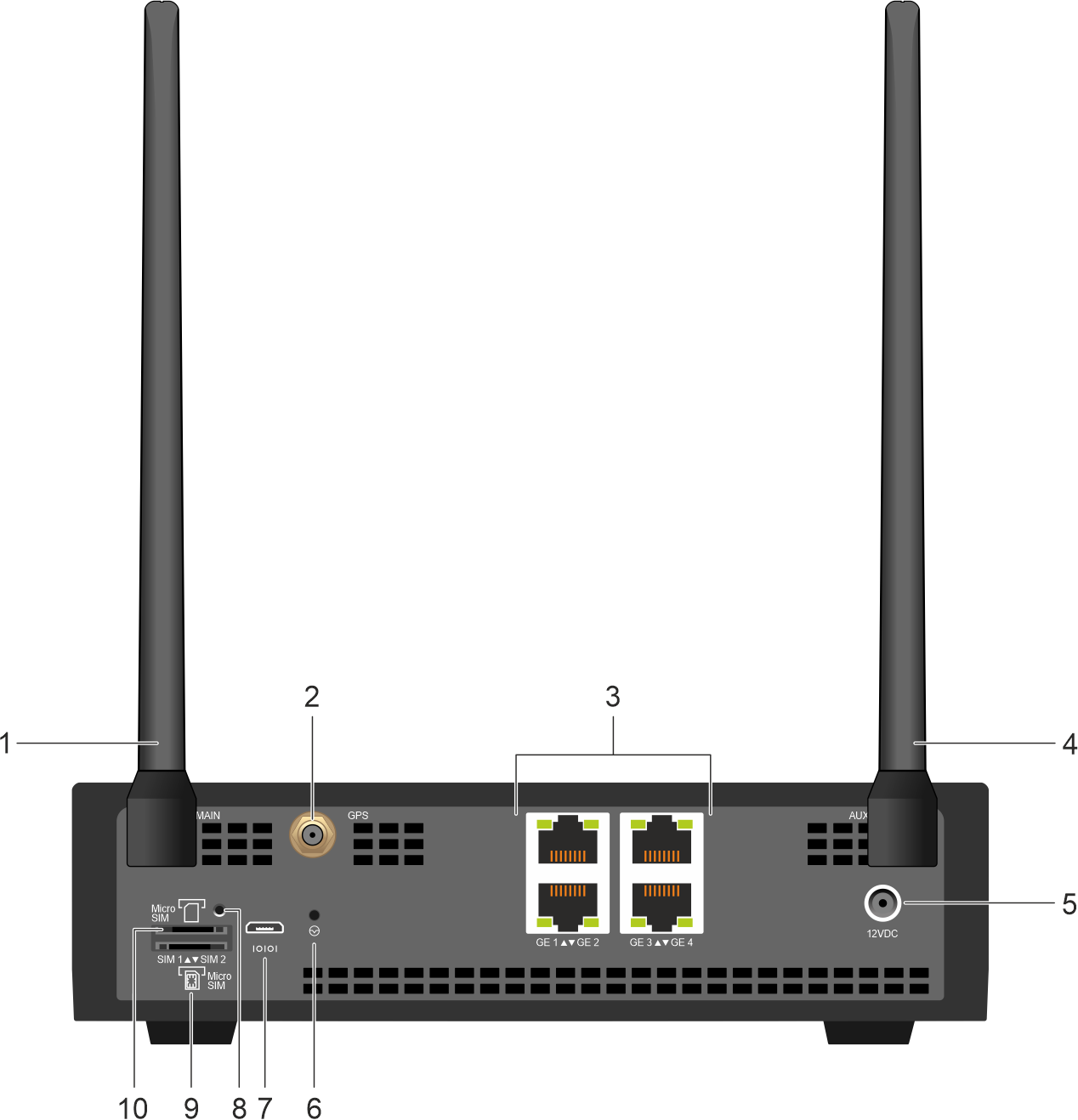
The VEP1420-LTE switch is mounted horizontally. Meaning, the switch sits on its four rubber feet and you can install both antennas into a vertical position as shown in Figure 2. The VEP1420-LTE rear view.
WWAN antenna specifications
| Electrical property | Details | Notes |
|---|---|---|
| Frequency range | 615-960 MHz, 1710-2170, 2300-2700, 3300-3800, 4100-4900, 5150-5925 MHz |
|
| Impedance | 50 ohms | N/A |
| VSWR | 3:1 Max | N/A |
| Return loss | 6 dBm Min | N/A |
| Radiation | Omni-directional | N/A |
| Gain | Dependent on the frequency band. | N/A |
| Polarization | Linear, Vertical | N/A |
| Max power | 1 W (30 dBm) | N/A |
| Connector | SMA-M (straight plug) - standard | N/A |
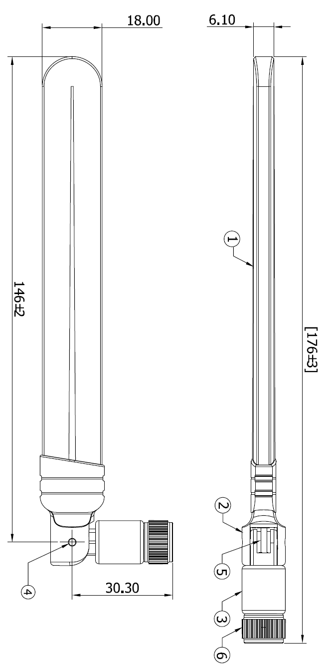
| Dimensions |
| N/A |
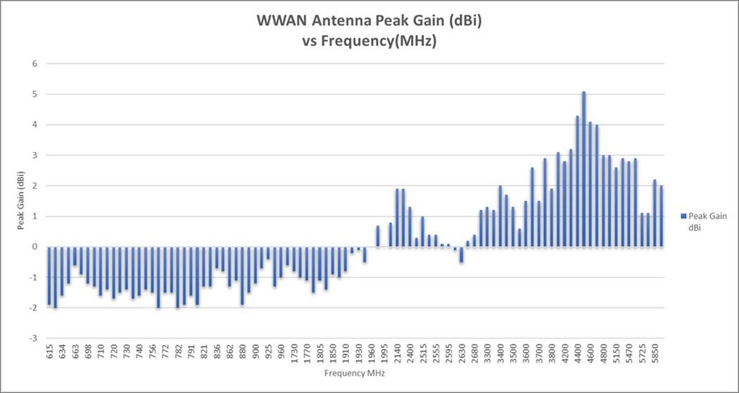
WWAN antenna peak gain
The following figure plots the peak gain of the antenna in dBi for the VEP1420-LTE. Peak gain is highest at 4500 MHz measuring 5.1 dBm and lowest in the low bands approximately -2 dBi.
The peak gain of the antenna at any frequency, along with the conducting power of the module and any cable losses, determines the Equivalent Isotropic Radiated Power (EIRP) of the VEP1420-LTE.
WWAN antenna efficiency
The following figure plots the efficiency of the antenna in % for the VEP1420-LTE. The antenna efficiency (provided in % or dBm) determines how well the device transmits or receives across the bands it is tuned for.
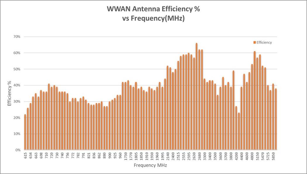
The following table summarizes the efficiency corresponding to the three band ranges for the WWAN antennas.
| Band range | Frequency Range (MHz) | Antenna efficiency (%) | Antenna efficiency (dB) |
|---|---|---|---|
| Low band | 615-960 | 22-41 | -6.6 to -3.9 |
| Midband | 1710-2700 | 36-55 | -4.4 to -2.6 |
| High band | 3300-5925 | 22-60 | -6.6 to -2.2 |
The following table provides the Total Radiated Power (TRP) that can be expected based on a fixed conductivity power of 23 dBm (typical LTE Tx from module) over a range of antenna efficiencies from 10-100%. The TRP values (in dBm) shown in the table are also based on a perfectly matched system (antenna impedance=50, ohms or VSWR=1). Actual antennas are never perfectly matched across all frequencies. As a result, some power is transmitted and some is reflected (VSWR >1). However, the table can serve as a guideline for the TRP as a system for the VEP1420-LTE based on the antenna efficiencies for the WWAN antenna provided in the previous table.
| Antenna efficiency (%) | Antenna efficiency (dB) | LTE conductivity power (dBm) | Total radiated power (dBm) |
|---|---|---|---|
| 10 | -10.0 | 23 | 13.0 |
| 20 | -7.0 | 23 | 16.0 |
| 30 | -5.2 | 23 | 17.8 |
| 40 | -4.0 | 23 | 19.0 |
| 50 | -3.0 | 23 | 20.0 |
| 60 | -2.2 | 23 | 20.8 |
| 70 | -1.5 | 23 | 21.5 |
| 80 | -1.0 | 23 | 22.0 |
| 90 | -0.5 | 23 | 22.5 |
| 100 | 0.0 | 23 | 23.0 |
WWAN antenna guidelines
The VEP1420-LTE has two ports for the WWAN antennas to connect to: MAIN and AUX. Following are the recommendations for optimal WWAN performance:
- For any orientation of the VEP1420-LTE, keep the two WWAN antennas away from metal objects or large surfaces that could detune the antenna. The more clearance from any metal object, the better the antenna behaves to its tuned frequencies.
- When the switch is wall-mounted, the WWAN antennas may perform better if you bend the antennas away from the wall. You can naturally bend the antennas to hold positions at 45 and 90-degree angles to vertical.
- When the switch sits normally (on four rubber feet), both WWAN antennas should point up vertically or at 45-degree angles (away from each other).
- Ensure that the screwed connections of the antenna (SMA) are hand tight to provide good contact between the WWAN antenna and the VEP1420-LTE.
- The VEP1420-LTE requires at least one WWAN antenna installed (on MAIN port of back panel) to function. This position provides both Tx and Rx functionality. The second WWAN antenna (AUX on back panel) provides diversity receiver functionality to improve WWAN download speeds and to provide GNSS functionality on this WWAN antenna.
- For use cases where improved GNSS functionality is required, beyond what is provided by the WWAN antenna on AUX port, you can purchase a separate dedicated GPS active antenna to connect to the GNSS port of the back panel (not supplied by Dell). For more information, see GNSS specifications.
WiFi specifications
The models VEP1420 and VEP1420-LTE support the latest WiFi6 (802.11ax) standard with 2x2 MIMO using two internal antennas. WiFi6 functions both on 2.4 GHz and 5 GHz band. It is also backward compatible to all previous WiFi Standards including 802.11(b,a,g,n,ac) - also referred to as WiFi1 through WiFi5.
Following are the WiFi specifications:
- WLE3002HX module using Qualcomm Atheros QCN6024
- 2.4 GHz, 2x2 MU-MIMO OFDMA: Up to 573 Mbps physical data rate
- 5 GHz, 2x2 MU-MIMO OFDMA: Up to 2402 Mbps physical data rate
- Dual-band selectable (2.4 GHz or 5 GHz)
- Supports Dynamic Frequency Selection (DFS)
- Supports up to 128 client devices
NOTE:Client devices must support the same WiFi 6 standard and dual antennas to achieve the maximum data rate of the VEP1420-LTE.
- 2.4 GHz band - supports 20 MHz & 40 MHz bandwidths.
- 5 GHz band - supports 20,40,80,160 MHz bandwidths.
WiFi transmitter
The transmitter output power depends on the mode - 802.11 a,b,g,n,ac,ax - and the modulation employed. For example, the maximum power that is transmitted in the 2.4 GHz band can be as high as 23 dBm (802.11b mode, all modulations) or as low as 16 dBm (802.11 ax mode, MCS11 modulation) using 2x2 MIMO.
Example output power for 802.11ax in the 5 GHz band using any of the 4 available channel bandwidths (20, 40, 80, 160 MHz) across the available modulation rates (MCS0 to MCS11), transmitting on two antennas. The output power in the 2.4 GHz band is the same for all modulations shown. However, this output power attribute is supported only on 20 MHz and 40 MHz channel bandwidths.
| Bandwidths | Modulation rate | Output power (dBm) 2x2 MIMO |
|---|---|---|
| 5 GHz 802.11ax @20, 40, 80 MHz or 160 MHz channel bandwidth | MCS0 | 23 |
| MCS1 | 23 | |
| MCS2 | 23 | |
| MCS3 | 22 | |
| MCS4 | 22 | |
| MCS5 | 21 | |
| MCS6 | 20 | |
| MCS7 | 19 | |
| MCS8 | 18 | |
| MCS9 | 17 | |
| MCS10 | 16 | |
| MCS11 | 16 |
WiFi Receiver
The WiFi receiver functions with varying degrees of sensitivity depending on both the mode of operation and the modulation employed. You can achieve higher degrees of receiver sensitivity at lower modulations (lower data rates). However, at higher modulations (higher data rate), the sensitivity of the radio decreases and the receiver requires a stronger RF link to maintain.
This sensitivity function implies that WiFi client devices that are closer maintain a higher data rate than client devices that are further away from the VEP1420. Devices that are further away or that have other interferences degrading the signal, cannot operate at the highest data rate. These devices automatically drop to lower data rates to maintain the RF link between them. As such, maintaining a strong RF link between the client device and the VEP1420 allows you to achieve maximum data rates.
WiFi data rates
At maximum modulation (MCS11) the date rate can reach up to 574 Mbps in the 2.4 GHz band using 40 MHz channel. For the 5 GHz band, using a 160 MHz channel, the maximum speed increases to 2402 Mbps.
The WiFi module automatically adjusts its modulation (data rate) based on the signal quality received. The mode of operation (802.11a,b,g,n,ac,ax), guard interval, channel bandwidth and MCS rate determines the maximum data rate possible.
The following table shows the maximum theoretical data rates for each modulation (MCS) based on two internal antennas. The highlighted values are the maximums possible for 2.4 GHz and 5 GHz respectively.
| WiFi6 802.11ax Data rates | Channel BW | 20 MHz | 40 MHz | 80 MHz | 160 MHz | ||
|---|---|---|---|---|---|---|---|
| Guard interval | Short | Short | Short | Short | |||
| MCS | Spatial Streams | Modulation | Coding R | Data rate Mbps | Data rate Mbps | Data rate Mbps | Data rate Mbps |
| 0 | 2 | BPKS | 1/2 | 17.2 | 34.4 | 72.1 | 144.1 |
| 1 | 2 | QPKS | 1/2 | 34.4 | 68.8 | 144.1 | 288.2 |
| 2 | 2 | QPKS | 3/4 | 51.6 | 103.2 | 216.2 | 432.4 |
| 3 | 2 | 16-QAM | 1/2 | 68.8 | 137.6 | 288.2 | 576.5 |
| 4 | 2 | 16-QAM | 3/4 | 103.2 | 206.5 | 432.4 | 864.7 |
| 5 | 2 | 64-QAM | 2/3 | 137.6 | 275.3 | 576.5 | 1152.9 |
| 6 | 2 | 64-QAM | 3/4 | 154.9 | 309.7 | 648.5 | 1297.1 |
| 7 | 2 | 64-QAM | 5/6 | 172.1 | 344.1 | 720.6 | 1441.2 |
| 8 | 2 | 256-QAM | 3/4 | 206.5 | 412.9 | 864.7 | 1729.4 |
| 9 | 2 | 256-QAM | 5/6 | 229.4 | 458.8 | 960.8 | 1921.6 |
| 10 | 2 | 1024-QAM | 3/4 | 258.1 | 516.2 | 1080.9 | 2161.8 |
| 11 | 2 | 1024-QAM | 5/6 | 286.8 | 573.5 | 1201.0 | 2402.0 |
| WiFi5 802.11ac Data rates | Channel BW | 20 MHz | 40 MHz | 80 MHz | 160 MHz | ||
|---|---|---|---|---|---|---|---|
| Guard interval | Short | Short | Short | Short | |||
| MCS | Spatial Streams | Modulation | Coding R | Data rate Mbps | Data rate Mbps | Data rate Mbps | Data rate Mbps |
| 0 | 2.0 | BPKS | 1/2 | 14.4 | 30.0 | 65.0 | 130.0 |
| 1 | 2.0 | QPKS | 1/2 | 28.9 | 60.0 | 130.0 | 260.0 |
| 2 | 2.0 | QPKS | 3/4 | 43.3 | 90.0 | 195.0 | 390.0 |
| 3 | 2.0 | 16-QAM | 1/2 | 57.8 | 120.0 | 260.0 | 520.0 |
| 4 | 2.0 | 16-QAM | 3/4 | 86.7 | 180.0 | 390.0 | 780.0 |
| 5 | 2.0 | 64-QAM | 2/3 | 115.6 | 240.0 | 520.0 | 1040.0 |
| 6 | 2.0 | 64-QAM | 3/4 | 130.0 | 270.0 | 585.0 | 1170.0 |
| 7 | 2.0 | 64-QAM | 5/6 | 144.4 | 300.0 | 650.0 | 1300.0 |
| 8 | 2.0 | 256-QAM | 3/4 | 173.0 | 360.0 | 780.0 | 1560.0 |
| 9 | 2.0 | 256-QAM | 5/6 | N/A | 400.0 | 866.7 | 1733.3 |
| WiFi4 802.11n Data rates | Channel BW | 20 MHz | 40 MHz | ||
|---|---|---|---|---|---|
| Guard interval | Short | Short | |||
| MCS | Spatial Streams | Modulation | Coding R | Data rate Mbps | Data rate Mbps |
| 8 | 2 | BPKS | 1/2 | 14.4 | 30.0 |
| 9 | 2 | QPKS | 1/2 | 28.9 | 60.0 |
| 10 | 2 | QPKS | 3/4 | 43.3 | 90.0 |
| 11 | 2 | 16-QAM | 1/2 | 57.8 | 120.0 |
| 12 | 2 | 16-QAM | 3/4 | 86.7 | 180.0 |
| 13 | 2 | 64-QAM | 2/3 | 115.6 | 240.0 |
| 14 | 2 | 64-QAM | 3/4 | 130.0 | 270.0 |
| 15 | 2 | 64-QAM | 5/6 | 144.4 | 300.0 |
WiFi antennas
The two WiFi antennas on the models VEP1420 and VEP1420-LTE are located internally toward the left and right sides of the switch. They support both 2.4 GHz and 5 GHz bands and are connected internally to the WiFi 802.11ax module.
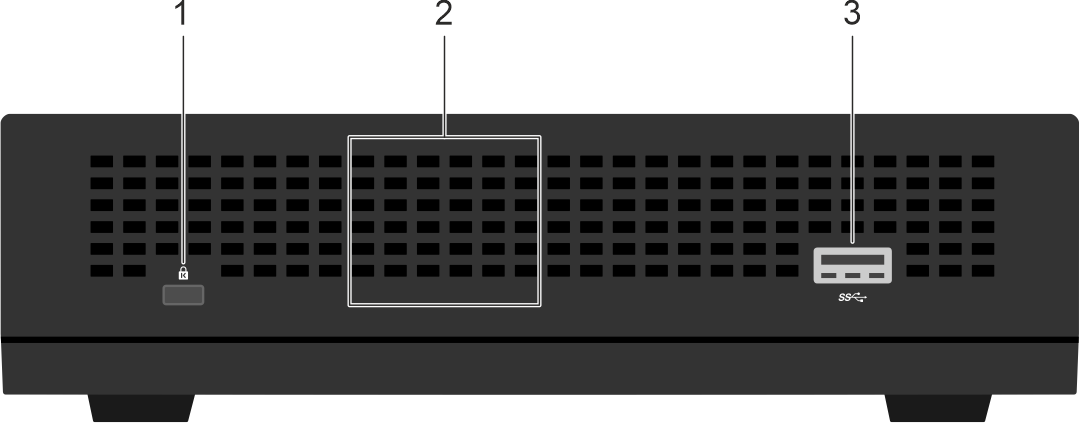
| Figure legend | Description |
|---|---|
| 1 | Security lock port. |
| 2 | Location of the Internal antenna (Right) on the VEP1420-LTE and VEP1420. |
| 3 | Micro USB port. |
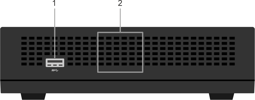
| Figure legend | Description |
|---|---|
| 1 | Micro USB port. |
| 2 | Location of the Internal antenna (Left) on the VEP1420-LTE and VEP1420. |
Internal WiFi antenna guidelines
Following are the guidelines for the internal WiFi antennas:
- Steer clear of metal objects or walls from the immediate left and right sides of the switch to ensure good WiFi antenna performance.
- Do not place any object on the top surface of the VEP1420 and VEP1420-LTE that could potentially affect WiFi performance.
GNSS specifications
The VEP1420-LTE supports the Global Navigation Satellite System (GNSS).
GNSS band support
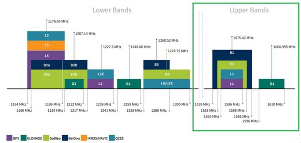
There are multiple bands within the GNSS systems in use around the world. However, the VEP1420-LTE only supports the UPPER BANDS as shown in the following table:
| GNSS | Upper Band | Frequency | Type of GNSS |
|---|---|---|---|
| GPS | L1 | 1565 MHz–1592 MHz | US satellite system |
| GLONASS | G1 | 1596 MHz–1610 MHz | Russian satellite system |
| Galileo | E1 | 1563 MHz–1588 MHz | European satellite system |
| Beidou | B1 | 1559 MHz–1592 MHz | China satellite system |
The VEP1420-LTE also supports QZSS, which is a regional satellite navigation system to augment GPS to provide more accuracy in the Asia-Oceania region.
The following figure provides a graphical representation of the upper GNSS bands that the VEP1420-LTE supports:
GNSS performance specifications
If the GNSS receiver is provided adequate RF signal, then the GNSS receiver performs according to the specifications described in the following table. If acquisition times after a cold start drop below one minute, then the RF signals to the GNSS receiver may not be optimal. As a result, the receiver performance could be degraded.
| GNSS figure of merit | Description | Notes |
|---|---|---|
| Acquisition time |
| NOTE:A Cold start means that the GNSS receiver has no information about its position. A Hot start means that the GNSS receiver already has current almanac, ephemeris, time, and position data.
|
| Accuracy | Horizontal:
Altitude:
Velocity:
| NOTE: Accuracy is measured using an RF signal of -135 dBm on the RF port of the receiver.
|
Receiver sensitivity
| Sensitivities
| N/A |
GNSS antenna support options
The GNSS functionality is available on the VEP1420-LTE:
- Standard method - This method uses the WWAN antenna that is attached to the AUX RF port.
- Optional method - This method uses a GNSS active antenna (not provided with the VEP1420-LTE) that installs on the GPS port.
| Figure legend | Antenna port | Description |
|---|---|---|
| 2 | GPS | GPS Rx port that supports GNSS Rx with a dedicated active GNSS antenna. |
| 4 | AUX | AUX RF port that supports GNSS Rx using WWAN antenna. |
The VEP1420-LTE switch supports GNSS through the WWAN paddle antenna that is mounted to the AUX receiver port. However, the module port must be configured such that it is set correctly to the AUX port for GNSS functionality. For most applications, the WWAN antenna that is provided and mounted to the AUX port is sufficient to provide reasonable GNSS performance. For more details, see the GNSS performance specifications section.
Configuring GNSS functionality for the AUX portThe AUX port on the VEP1420-LTE supports GNSS with the WWAN antenna. The following configuration commands ensure that the AUX RF port is configured to receive GNSS signals:
| Configuration commands that enable usage of AUX RF port for GNSS | AT commands | Notes |
|---|---|---|
| Unlock module commands. | at!entercnd="A710" | NOTE: Required to change certain module settings.
|
| Select AUX RF port to use for GNSS. | at!custom="GPSSEL",1 | NOTE: GNSS Port options on the VEP1420-LTE:
|
In case the standard passive WWAN antenna lacks enough signal to provide good performance, you can improve the GNSS support using an external active GNSS antenna. Longer than expected Time to First Fix (TTFF) or inability to get a position fix at all can be an indicator of poor performance. The degradation in performance occurs when the GNSS receiver is unable to achieve a strong enough RF signal from the satellites orbiting the Earth.
To mitigate issues with GNSS poor performance, you can mount a GNSS active antenna to the GPS RF port of the VEP1420-LTE. You can position the GNSS active antenna more optimally to receive low-level outdoor satellite signals. For example, near a window or on a roof, as the antenna has a long coax cable that is provided with it. If there are issues while using the WWAN passive antenna, the additional gain from the active embedded Low Noise Amplifier (LNA) mitigates the cable loss and provides better performance for the GNSS operation.
Configuring the GPS port for usage with an active antenna
Alternatively, an active GNSS antenna can be purchased to use on the GPS port and configured for use.
In order for, the active GNSS antenna to work as designed when installed on the GPS port, the integrated LNA of the antenna requires a voltage supply from the LTE module. The GNSS antenna also requires the RF port to be set correctly to the GPS port on the VEP1420-LTE. Both functions are controlled with AT commands that are sent to the module. If an active GNSS antenna is used, you must send the AT commands to the module.
The following table describes the commands necessary to support the GPS RF port instead of the AUX RF port:
| Configuration commands that enable usage of GPS RF port for GNSS | AT command | Description |
|---|---|---|
| Unlock the module command. | at!entercnd="A710" | Changes module settings. |
| Select GPS RF port for GNSS use. | at!custom="GPSSEL",0 | Sets GNSS port options on the VEP1420-LTE. Following are the options available with this command:
|
| Set GPS port voltage | at+want=1 | Provides 3.15 V output on the RF pin corresponding to the GPS port.
NOTE:This command is applicable only to the GPS RF port and not to the AUX port. This voltage is meant for use with an active GNSS antenna.
|
GNSS antenna specifications for use with GPS port
If the WWAN antenna does not meet expected GNSS performance specifications, Dell Technologies recommends an active GNSS antenna. See the following table for the specifications for using an active GNSS antenna.
| GNSS active antenna specifications for the GPS port | Notes | |
|---|---|---|
| Impedance | 50 ohms | N/A |
| Antenna type | Active | NOTE:Requires voltage input to power the internal LNA in the antenna.
|
| RF port type | SMA plug | NOTE:Requires to plug into the SMA jack on the VEP1420-LTE GPS port.
|
| Frequency range options | 1559 MHz–1610 MHz 1559 MHz–1592 MHz | NOTE: Covers the following upper bands: B1, E1, G1, and L1.
|
NOTE: Covers the B1, E1, and L1 bands, but not the G1 band.
| ||
| Center frequency | ~1575 MHz | NOTE:The following bands are centered at this frequency: B1, E1, G1, and L1.
|
| VSWR | <2.5:1 | N/A |
| Polarization | >0 dB | NOTE:Linear or RHCP.
|
| DC input of antenna | 3.15 V +/- 0.15 V | NOTE:The active GNSS antenna can support a wider range of voltages, but must support ~3 V to work with the GPS port of the VEP1420-LTE. A voltage of 3.15 V is supplied by the internal module to the active antenna.
|
| LNA gain | 15 dB–30 dB | N/A |
| Noise figure | <3 dB | N/A |
| Power consumption | <100 mA | NOTE: This power is the maximum power that is provided by the embedded module.
|
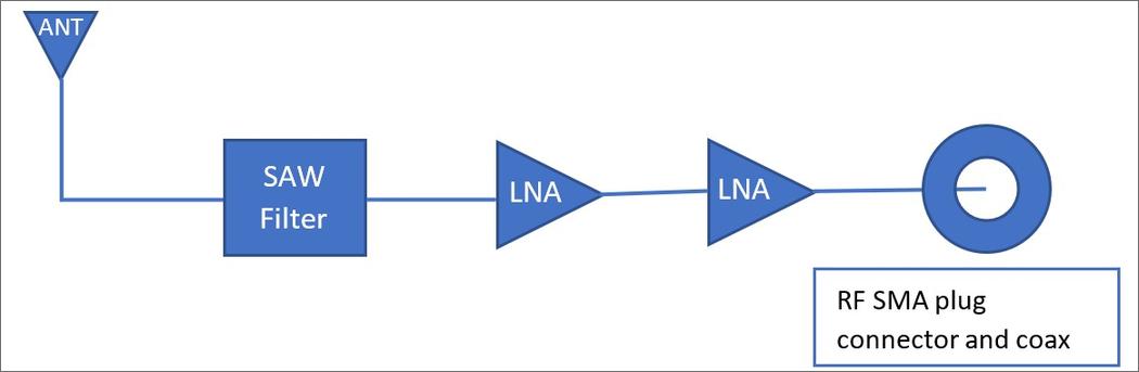
The following figure shows an example block diagram of the internal components of an active GNSS antenna meant for use on the GPS port of the VEP1420-LTE. The active GNSS antenna may have one or two internal LNAs. The active GNSS antenna should have at least one SAW filter that is positioned after the antenna and before the first LNA to avoid degradation due to WWAN transmissions such as LTE.
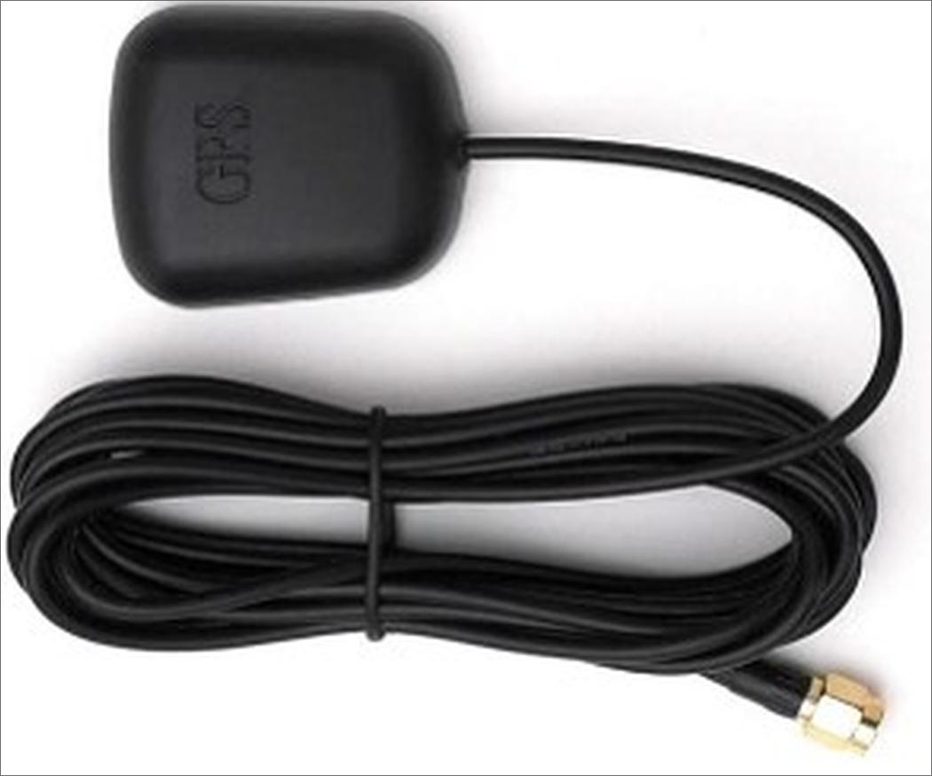
The following figure shows a GNSS antenna cable that can connect to the GPS port:
Validating GNSS performance
You can validate GNSS performance using the following two methods:
- GNSS validation - Method 1 - Using the Linux command-line tool that is provided in the DIAG operating system of the VEP1420-LTE called em75xx.sh.
- GNSS validation - Method 2 - Using AT commands directly on the embedded modem.
Perform the following command from the Linux command line of the DIAG operating system:
root@dell-diag-os:~# em75xx.sh gps run 1
You can view the example output using the following command:
root@dell-diag-os:~# em75xx.sh gps run 1
for EM75xx
Starting GPS Location Fixing.
===================================================================
Event Position Report
Session Status: 0
Session ID: 1
Latitude: 37.294811
Longitude: -121.982541
Horizontal position uncertainty: 10.000000
Semi-minor axis of horizontal elliptical uncertainty: 6.000000
Semi-major axis of horizontal elliptical uncertainty: 8.000000
Elliptical Horizontal Uncertainty Azimuth: 140.625000
Horizontal Confidence: 39
Horizontal Reliability: 2
Horizontal Speed: 0.000000
Speed Uncertainty: 0.205183
Altitude With Respect to Ellipsoid: 30.031921
Altitude With Respect to Sea Level: 58.133141
Vertical Uncertainty: 6.000000
Vertical Reliability: 2
Vertical Speed: 0.000000
Magnetic Deviation: 15.000000
Technology Mask: 1
Position dilution of precision: 2.200000
Horizontal dilution of precision: 2.000000
Vertical dilution of precision: 0.900000
UTC Timestamp: 0.000000
Leap Seconds: 18
GPS Week: 2279
Amount of time into the current GPS week: 509225000
Time Source: 7
Usage Mask: 0
Aided Indicator Mask: 0
Fix ID: 1
GNSS SV Used List Length: 8
GNSS SVs Used List: 2
GNSS SVs Used List: 21
GNSS SVs Used List: 28
GNSS SVs Used List: 31
GNSS SVs Used List: 32
GNSS SVs Used List: 66
GNSS SVs Used List: 75
GNSS SVs Used List: 303
Altitude Assumed: 1
===================================================================
Total: 1 fix count(s).
GNSS validation - Method 2
You can also verify GNSS using AT commands. When you use this method, it provides additional details such as the Signal to Noise Ratio (SNR) for each satellite vehicle (SV). These additional details are not available when using the DIAG operating system em75xx.sh tool.
| GNSS operation to validate | AT command | Description |
|---|---|---|
| Unlock the module command. | at!entercnd="A710" | Changes certain module settings. |
| GPS session | at!gpsend=0,255 | Ends current session before starting a new one. |
| GPS cold start | at!gpscoldstart | Initiates a GPS cold start. |
| GPS position fix | at!gpsfix=1,90,10 | Initiates a GPS position fix. The following are the parameters:
|
| Query satellites | at!gpssatinfo? | Provides a list of satellite vehicles observed. |
| Query fix status | at!gpsstatus? | Provides the status of the GPS position fix. |
| Query the location | at!gpsloc? | Provides location details in latitude and longitude. |
For a cold start, Time to First Fix (TTFF), the location fix for GPS occurs within 35 s with good to excellent Signal to Noise Ratio (SNR). The following table provides general guidelines to read SNR information reported by a Satellite Vehicle (SV) using the at!gpssatinfo? Command:
| Satellite Vehicle (SV) Signal to Noise Ratio (SNR) (dB) | SNR quality | Expected TTFF performance |
|---|---|---|
| <30 | Poor | No GPS position fix attainable or long TTFF. |
| 30–33 | Ok | Longer TTFF times before establishing a fix. Expect several minutes. |
| 33–36 | Good | Slightly longer than expected TTFF. |
| 36–39 | Very Good | Expected GNSS Performance Specifications with multiple SVs reporting these values. |
| >=40 | Excellent | Expected GNSS Performance Specifications with multiple SVs reporting these values. |
Sending AT commands to the embedded module
If you are using the GPS port with a GNSS active antenna or the AUX port with the WWAN antenna, you must configure the ports first before usage. For more details, see the GNSS antenna support options section.
In order to send AT commands to the module, you must use the Linux program - Minicom - to communicate serially with the modem while the modem manager is not running. The following list provides steps to configure the RF port to use and validate its performance:
- From the Linux command line, stop the modem manager and verify whether it has stopped running.
systemctl stop ModemManager
mmcli -L
Figure 5. Stop the Modem manager. Stop the Modem manager 
- Open the
Minicom to communicate with the modem.
minicom -D /dev/ttyUSB2
Figure 6. Open Minicom. Open Minicom 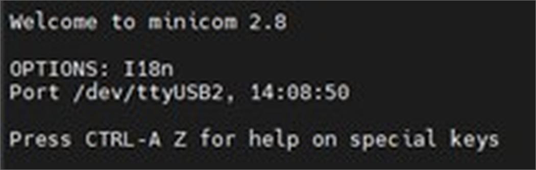
- In
Minicom, enter the
ati command to ensure communication. If the modem responds, then the modem is communicating properly.
Figure 7. Modem response. Modem response 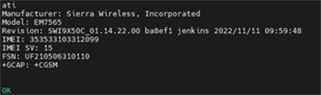
- Set the RF port to the wanted GNSS port of the VEP1420-LTE as described in the
GNSS antenna support options section.
NOTE:Choose only one of the following options:
- WWAN antenna (Standard) - These commands set the GNSS functionality to the AUX port.
Figure 8. RF port configuration command (AUX port). RF port configuration command (AUX port) 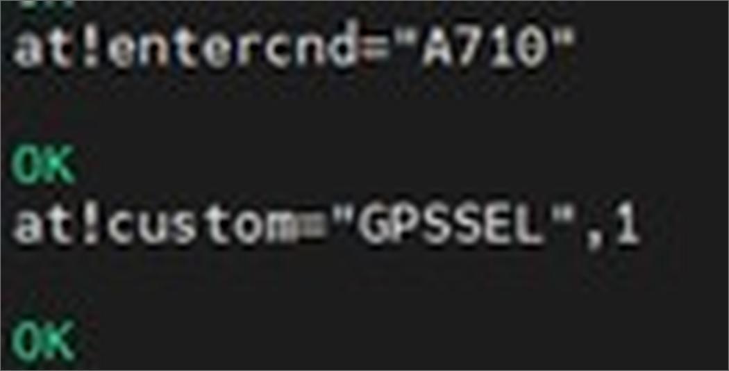
- Active GNSS antenna (Purchased separately) - Enter the commands shown in the following Figure to switch to the GPS port and to set the voltage for this port:
Figure 9. RF port configuration (GPS port) and active voltage AT commands. RF port configuration (GPS port) and active voltage AT commands 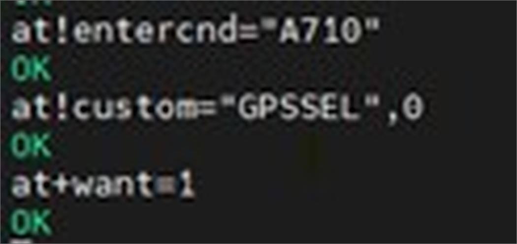
- WWAN antenna (Standard) - These commands set the GNSS functionality to the AUX port.
- If you use the WWAN antenna on the AUX port, ensure that it is installed.
- If you use the active antenna on the GPS port, ensure that it is installed.
- Configure the module to initiate a GPS position fix. To achieve a position fix, use the
GNSS validation - Method 2 . You must query the GPS position fix status multiple times until a fix is determined. Use the
at!gpsstatus? Command for this purpose. The following Figure shows that the multiple queries ran on the Minicom tool:
Figure 10. GPS position fix queries. GPS position fix queries 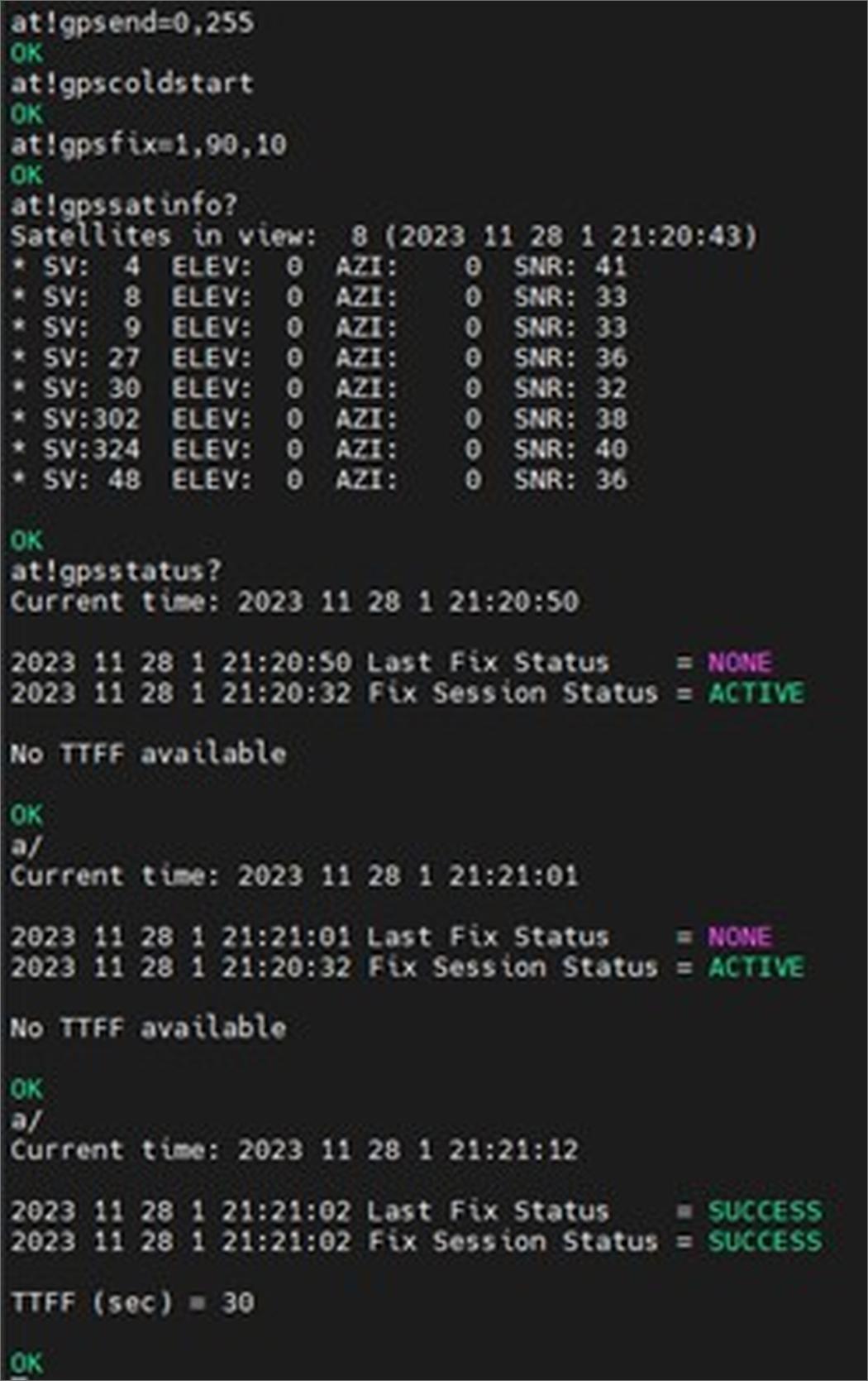
- After Last Fix Status=SUCCESS and TTFF is provided, enter the location query command -
at!gpsloc? - to establish the latitude and longitude of the 3D position fix.
Figure 11. 3D GPS position fix. 3D GPS position fix 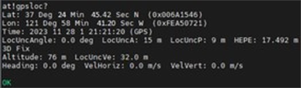
- After the GPS functionality is verified on the wanted port, exit Minicom. Enter
CTRL-A followed by
z and
x. Select
Yes and press
Enter to exit Minicom.
Figure 12. Exit Minicom. Exit Minicom 
- Restart the modem manager to allow WWAN network connectivity and verify that the modem manager has restarted using the following commands:
systemctl start ModemManager
mmcli -S
mmcli -L
Figure 13. Restart modem manager. Restart modem manager 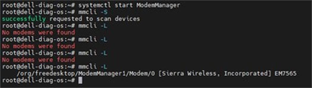
Chassis physical design
This section details the external design aspects corresponding to the VEP1420.

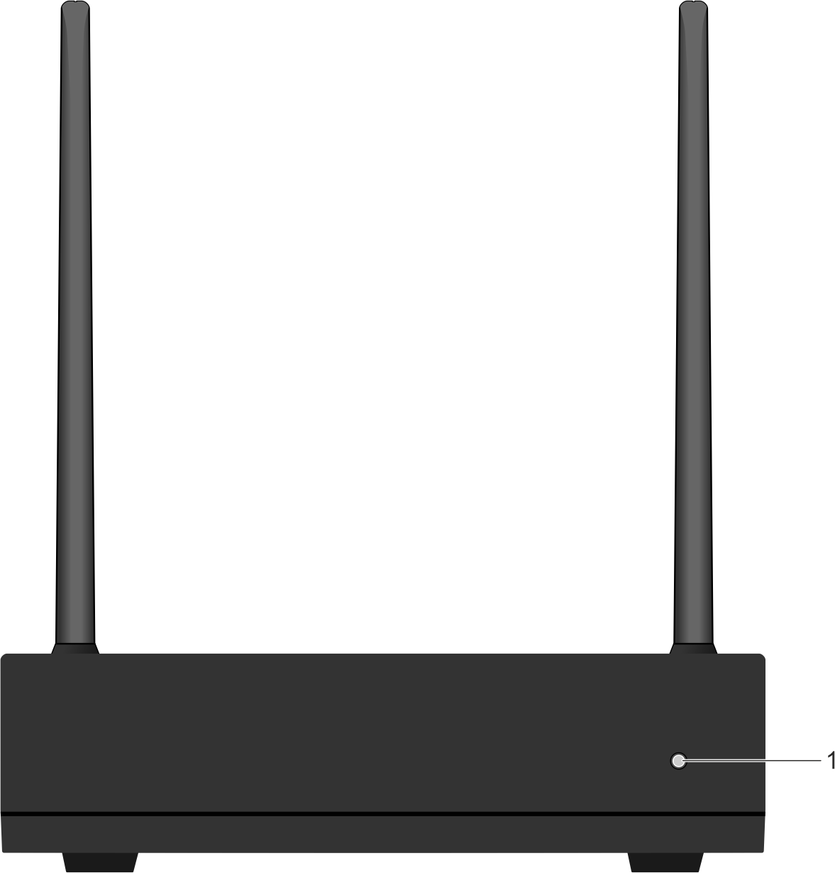
- System status indicator LED
- USB port.
- Location of the Internal antenna (Left).
- Security lock port.
- Location of the Internal antenna (Right).
- USB port
NOTE:An additional USB port is on the opposite side of the system.
| Color | Status |
|---|---|
| Solid Green |
|
| Solid White |
|
| Solid Red |
|
| LED off |
|
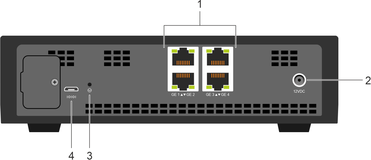
- RJ45 ports
- Power connection port
- Reset button
NOTE:For more information, see Table 21. Reset button behavior.
- Micro USB serial console port
- SMA jack mount for the main antenna
- SMA jack mount for the GPS antenna
- RJ 45 ports
- SMA jack mount for the auxiliary antenna
- Power connection port
- Reset button
NOTE:For more information, see Table 21. Reset button behavior.
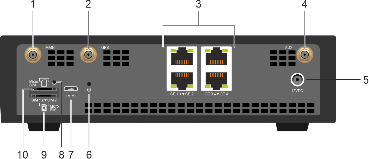
- SMA jack mount for the main antenna
- SMA jack mount for the GPS antenna
- RJ45 ports
- SMA jack mount for the auxiliary antenna
- Power connection port
- Reset button
NOTE:For more information, see Table 21. Reset button behavior.
- Micro USB serial console port
- Port cover screw hole
- Micro SIM Slot 2
- Micro SIM Slot 1
- Main antenna
- SMA jack mount for the GPS antenna
- RJ45 ports
- Auxiliary antenna
- Power connection port
- Reset button
NOTE:For more information, see Table 21. Reset button behavior.
- Micro USB serial console port
- Port cover screw hole
- Micro SIM Slot 2
- Micro SIM Slot 1
| Action | Behavior |
|---|---|
| Press the Reset button. When the system is powered off: | The system powers on |
| Parameter | Specification |
|---|---|
| Height | 5.2 cm (2.0 in) |
| Width | 20.8 cm (8.1 in) |
| Depth | 20.0 cm (7.9 in) |
| Chassis weight with factory-installed components |
|
| Parameter | Specification |
|---|---|
| Operating temperature | 0–40°C (32°F–104°F) continuously |
| Operating humidity |
|
| Storage temperature | –40°-70°C (–40° to 158°F) |
| Storage humidity | 5% to 90% (RH), noncondensing |
| Maximum operational altitude | 3,048 meters (10,000 ft) with no performance degradation to 950 meters (3117 ft) |
| Maximum nonoperational altitude | 10,668 meters (35,000 ft) |
| Parameter | Specification |
|---|---|
| Power supply | 110–240 VAC 50/60 Hz |
| Maximum current draw per system - AC |
|
| Power consumption | VEP1420N:
VEP1420:
VEP1420-LTE:
|
Safety standards and agency compliance certifications
- UL 62368-1, 3rd Edition
- Meets or exceeds Hi Pot and Ground Continuity testing per UL 62368-1.
- CSA 62368-1, 3rd Edition
- EN 62368-1, 3rd Edition
- IEC 62368-1, including all National Deviations and Group Differences
Product recycling and disposal
Waste electrical and electronic equipment (WEEE) directive for recovery, recycling, and reuse of IT and telecommunications products
You must recycle or discard this switch according to applicable local and national regulations. Dell Technologies encourages owners of information technology (IT) equipment to responsibly recycle their equipment when it is no longer needed. Dell Technologies offers various product return programs and services in several countries to assist equipment owners in recycling their IT products.Dell Technologies switches are labeled in accordance with European Directive 2002/96/EC concerning waste electrical and electronic equipment (WEEE). The Directive determines the framework for the return and recycling of used appliances as applicable throughout the European Union. This label is applied to various products to indicate that the product is not to be thrown away; but rather reclaimed upon end of life per this Directive.

In accordance with the European WEEE Directive, electrical and electronic equipment (EEE) is to be collected separately and to be reused, recycled, or recovered at the end of life. Users of EEE with the WEEE marking per Annex IV of the WEEE Directive, as shown above, must not dispose of end of life EEE as unsorted municipal waste, but use the collection framework available to customers for the return, recycling and recovery of WEEE. Customer participation is important to minimize any potential effects of EEE on the environment and human health due to the potential presence of hazardous substances in EEE.
Dell Technologies products, which fall within the scope of the WEEE, are labeled with the crossed-out wheelie-bin symbol, as shown above, as required by WEEE.
For information about Dell Technologies product recycling offerings, see the WEEE Recycling instructions on Support. For more information, contact the Dell Technologies Technical Assistance Center.
Agency compliance
The VEP1420 is designed to comply with the following safety and agency requirements:
USA Federal Communications Commission statement
1) This device may not cause harmful interference, and (2) this device must accept any interference received, including interference that may cause undesired operation.
This equipment has been tested and found to comply with the limits for a Class B digital device, pursuant to Part 15 of the FCC Rules.
These limits are designed to provide reasonable protection against harmful interference in a residential installation. This equipment generates, uses, and can radiate radio frequency energy and, if not installed and used in accordance with the instructions, may cause harmful interference to radio communications. However, there is no guarantee that interference will not occur in a particular installation. If this equipment does cause harmful interference to radio or TV reception, which can be determined by turning the equipment off and on, the user is encouraged to try to correct the interference by one or more of the following measures:
- Reorient or relocate the receiving antenna.
- Increase the separation between the equipment and receiver.
- Connect the equipment into an outlet on a circuit different from that to which the receiver is connected.
- Consult the dealer or an experienced radio or TV technician for help.
FCC Caution:
Any changes or modifications that are not expressly approved by the party responsible for compliance could void the authority of the user to operate this equipment.
This transmitter must not be co-located or operating with any other antenna or transmitter.
Radiation Exposure Statement:
This equipment complies with FCC radiation exposure limits set forth for an uncontrolled environment. This equipment should be installed and operated with a minimum distance 20 cm between the radiator and your body.
Canada ISED Conformance Statement
ISED, Class B
This Class B digital apparatus complies with Canadian ICES-003.
Notice: The Industry Canada regulations provide that changes or modifications that are not expressly approved by Dell Inc. could void your authority to operate this equipment.
This device complies with ISED license-exempt RSS standards. Operation is subject to the following two conditions: (1) this device may not cause interference, and (2) this device must accept any interference, including interference that may cause undesired operation of the device.
This device and its antennas must not be co-located or operating with any other antenna or transmitter, except tested integrated radios. The County Code Selection feature is disabled for products that are marketed in the US or Canada.
Radiation Exposure Statement:
The radiated output power of this device is below the ISED radio frequency exposure limits. This device has been evaluated for and shown compliant with the IC Radio Frequency (RF) Exposure limits. The device should be used in such a manner such that the potential for human contact during normal operation is minimized.
ISED, classe B
Cet appareil numérique de classe B est conforme à la norme canadienne ICES-003.
Avis : Dans le cadre des réglementations d'Industry Canada, vos droits d'utilisation de cet équipement peuvent être annulés si des changements ou modifications non expressément approuvés par Dell Inc. y sont apportés.
Cet appareil est conforme aux normes d'exemption de licence RSS d'Industry Canada. Son fonctionnement est soumis aux deux conditions suivantes : (1) cet appareil ne doit pas causer d'interférence et (2) cet appareil doit accepter toute interférence, notamment les interférences qui peuvent affecter son fonctionnement.
Cet appareil et son antenne ne doivent pas être situés ou fonctionner en conjonction avec autre antenne ou un autre émetteur, exception faites des radios intégrées qui ont été testées. La fonction de sélection de l'indicatif du pays est désactivée pour les produits commercialisés aux États-Unis et au Canada.
Informations sur l'exposition à la fréquence radio (FR):
La puissance rayonnée de sortie de cet appareil est inférieure aux limites d'exposition à la fréquence radio d'ISED. Cet appareil a été évalué et jugé conforme aux limites d'exposition à la fréquence radio (FR) d'IC. Cet appareil devrait être utilisé de manière à ce que le risque de contact humain au cours d'un fonctionnement normal soit réduit.
Brazil Conformation Statement
Brazil – ANATEL – SAR e RF Declaração
Informações regulamentares
Modelo de marketing (MMN)...........: Dell VEP1420
Modelo regulamentar (RMN)............: E71W
Tipo regulamentar (RTN)..................:E71W001

Este equipamento não tem direito à proteção contra interferência prejudicial e não pode causar interferência em sistemas devidamente autorizados.
Para maiores informações, consulte o site da ANATEL. www.anatel.gov.br
Envie uma solicitação para a caixa de correio da Dell Regulatory em Product_Compliance@dell.com caso precise de informações adicionais ou suporte em produtos Dell neste país.
Thailand Conformance Statement

The following is for radiocommunication equipment per act B.E. 2498:


European Union Conformance Statement
CE Notice
This product has been determined to be in compliance with 2006/95/EC (Low Voltage Directive), 2014/30/EU (EMC Directive), and amendments of the European Union. Versions of this product may have integrated modules or add-in cards supporting wireless and telecommunications operations. These wireless and telecommunications peripherals have been assessed as compliant in this product and, when present, are in compliance with 2014/53/EU (Radio Equipment Directive).
European Union, Class B
This Dell device is classified for use in a typical Class B domestic environment. A “Declaration of Conformity” in accordance with the preceding directives and standards has been made and is on file at Dell Products Europe BV, Limerick, Ireland.
Japan Conformance Statement
クラス B VCCI 基準について
クラス B VCCI の表示 があるワークステーションおよびオプション製品は、クラス B 情報技術装置です。これらの製品には、下記の項目が該当します 。
この装置は、情報処理装置等電波障害自主規制協議会 (VCCI)の基準に基づくクラス B 情報技術装置です。この装置、家庭環境で使用することを目的としていますが、この装置がラジオやテレビジョン受信機に近接して使用されると、受信障害を引き起こすことがあります。取扱説明書に従って正しい取り扱いをしてください 。
Warning: Use the AC power cables with Dell equipment only. Do not use Dell AC power cables with any unauthorized hardware.
本製品 に 同梱 いたしております 電源 コードセツ 卜 は、 本製品 専 用 です。
本電源コードセツ卜は、本製品以外の製品ならびに他の用途でこ使用いただくことは、出来ませ
ん。 製品本体には同梱され電源コードセツ卜を使用し、他製品の電源コードセツ卜を使用
しないで下さい。
India Conformance Statement
This product conforms to the relevant Essential Requirements of TEC, Department of Telecommunications, Ministry of Communications, Government of India, New Delhi-110001.
South Korea Conformance Statement
|
B급 기기 |
이 기기는 가정용(B급) 전자파적합기기로서 주로 가정에서 사용하는 것을 목적으로. |
|
(가정용 방송통신기자재) |
하며, 모든자역에서 사용할 수 있습니다. |
다음은 KCC 규정 준수에 따라 본 설명서에서 언급하고 있는 B등급 장치에 관한 것입니다.
|
인증 수취인 : |
Dell Inc. Global Product Compliance, Engineering and Environmental Affairs One Dell Way PS4-30 Round Rock, Texas 78682 USA 512-338-4400 |
|
장비 또는 모델명 : |
이 정보에 관한 제품 레이블을 참조하십시오 |
|
인증 번호 : |
KCC 로고 바로 밑에 있는 인증 번호를 참조하십시오 . |
|
제조일 : |
각각의 제품에는 제조 날짜가 인쇄되어 있습니다 . 이 날짜는 바코드 형태로 되어 있을 것입니다. |
|
제조국가 : |
이 정보에 관한 제품 레이블을 참조하십시오 . |
상기각각의 제품에는 제조 날짜가 인쇄되어 있습니다 .
Radio Regulatory Information
해당 무선설비는 전파혼신 가능성이 있으므로 인명안전과 관련된 서비스는 할 수 없음
Mexico Conformance Statement
Radio Regulatory Information
La operación de este equipo está sujeta a las siguientes dos condiciones:
- Es posible que este equipo o dispositivo no cause interferencia perjudicial y
-
Este equipo o dispositivo debe aceptar cualquier interferencia, incluyendo la que pueda causar su operación no deseada.
Taiwan Conformance Statement
Radio Regulatory Information
台灣 : 國家通訊傳播委員會
低功率電波輻射性電機管理辦法
第十二條經型式認證合格之低功率射頻電機,非經許可,公司、商號或使
用者均不得擅自變更頻率、加大功率或變更原設計之特性及功能。
第十四條低功率射頻電機之使用不得影響飛航安全及干擾合法通信;經發
現有干擾現象時,應立即停用,並改善至無干擾時方得繼續使用。
前項合法通信,指依電信法規定作業之無線電通信。低功率射頻電機須忍受合法通信或工業、科學及醫療用電波輻射性電機設備之干擾。